A two-section brake valve is used to control the actuators of the vehicle's service brake system. The two-section brake valve is mounted on the front shield of the cabin.
Disassembling and assembling the valve
For disassembling, the valve must be installed in a vice with soft jaws, securing it to the technological plugs screwed into housings 6 and 11 with the pusher 1 upwards.
Disassembling the valve must begin with dismantling the pusher 1, after which it is necessary to remove the plate 12 and the upper piston 9 as an assembly.
Disassembling the elastic element 10 from the upper piston 9 is carried out only in extreme cases, since this disrupts the adjustment of the stud position.
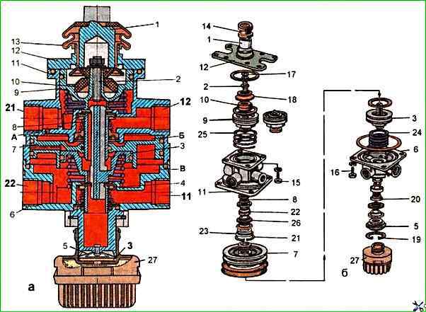
To do this, hold piston 9 through a cloth napkin and unscrew nut 17 and stud 2. After which the elastic element 10 can be easily removed from piston 9.
Turn the tap in a vice 180° and remove thrust ring 19 with round-nose pliers.
Remove valve 5 of the atmospheric outlet assembly and valve 4 of the lower section together with the rubber sealing ring, thrust ring and spring 24 from housing 6.
Unscrew bolts 16 and remove housing 6, holding it with your hand.
Remove spring 24 and small piston 3 from housing 11.
Having clamped them with two pliers through special gaskets, remove large piston 7.
To dismantle valve 8 of the upper section, use round-nose pliers to remove thrust ring 21 and remove the valve together with sleeve 23, support rings, conical spring 22, cap and rubber sealing rings.
To remove the noise muffler, use round-nose pliers to remove the lock ring.
After disassembling, the parts of the two-section brake valve must be washed with clean gasoline or acetone, dried and carefully inspected.
Cracks, hairlines and other defects visible to the eye are not allowed on the surface of the body parts.
The parts must be cleaned of rust and burnt-on deposits. All rubber parts must be replaced.
Before assembly, the parts of the two-section brake valve must be lubricated by hand with a thin layer of Tsiatim - 221 grease.
The valves, rubber sealing rings and other rubber parts must be assembled carefully, avoiding damage.
The presence of scratches, cuts and other defects on the surface of these parts is not allowed.
Assembly of the tap should begin with installing the valve of the upper section 8 in the housing 11.
The sequence of installation of the parts of the valve 8 should correspond to Fig. 1.
When installing the support ring 26, its flange should be oriented towards the conical spring 22.
Holding the valve with a mandrel, install the thrust ring 21 in the groove using round-nose pliers.
Next, it is necessary to install the large piston 7, the small piston 3, the spring 24, which differs from the spring 25 of the upper piston in its shorter length, the rubber sealing ring and the lower housing 6.
Fasten the lower housing 6 with bolts 16 with spring washers.
After this, it is necessary to install the atmospheric outlet valve assembly 5 in the housing 6 and secure it with a thrust ring 19 using round-nose pliers.
Turn the tap in a vice 180°.
Assemble the upper piston 9 with the elastic element 10, rubber ring and plate 18, tighten the pin 2.
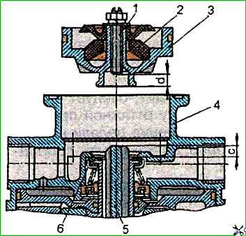
Before installing the upper piston 3 (Fig. 2) it is necessary to measure the distance "C" protruding the piston tail above the valve 6.
Adjust the distance d with stud 1, equal to C+0.8 mm, between the stud and the small piston 5 and lock the stud with a nut.
Install the assembled piston 9 (see Fig. 1) in the housing 11 on the spring 25 and, if necessary, press it with a clamp.
Then it is necessary to install the rubber sealing rings, plate 12 and pusher 1 in accordance with Fig. 1.
Adjusting and checking the two-section brake valve
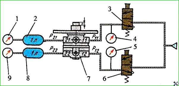
Install the valve on the test bench and connect it according to the diagram shown in Fig. 3. Then do the following.
Move the plunger three times. There should be no jamming and it should quickly return to its original position.
Apply air under a pressure of 0.75 MPa to terminals 11 and 12 and move the plunger to the stop and back three times.
The pressure in terminals 21 and 22 should change from 0 to the pressure in terminals 11 and 12 and back.
When the plunger is moved by h = 1.9-3.0 mm, pressure should appear in terminal 21.
When the pressure in terminal 21 reaches 0.05 MPa, the pressure in terminal 22 should be at least 0.025 MPa. In this case, the pusher stroke should exceed 1.9 mm.
The pressure lead in terminal 21 relative to the pressure in terminal 22 may be maintained over the entire pressure range, but should not exceed 0.025 MPa.
The initial pressure jump in terminals 21 and 22 should not exceed 0.02 MPa.
When the pressure in terminal 21 reaches 0.3 MPa, the pusher stroke should be 5.8-8.0 mm.
When the pressure in terminal 21 reaches 0.75 MPa, the pusher stroke should be 8.4-10.8 mm.
The total pusher stroke should be 12.5-15.7 mm.
With smooth movement of the pusher, the pressure at terminals 21 and 22 should smoothly increase after the initial jump, and when the pusher is released, — gradually decrease.
Apply air at a pressure of 0.75 MPa to terminal 11 and move the plunger to the stop. In this case, the pressure in terminal 21 should change from 0 to 0.75 MPa.
Apply air at a pressure of 0.75 MPa to terminals 12 and move the plunger to the stop. In this case, the pressure in terminal 22 should change from 0 to 0.75 MPa.
When checking the valve for leaks, it should be leak-proof in any position of the plunger. The check must be performed:
- with the pusher released and a pressure of 0.75 MPa in terminals 11 and 12;
- with the pusher pressed all the way and a pressure of 0.75 MPa in terminals 11 and 12;
- with the pusher pressed all the way and a pressure of 0.75 MPa in terminal 11,
When soaping, the appearance of air bubbles is not allowed for 1 min.
After installing the valve on the bus, it is necessary to adjust its drive.
The drive of the two-section brake valve consists of a pedal and a roller on an axis, installed with an eccentricity, with a nut.
The desired position of the pedal on the cabin floor is set by rotating the axis of the roller installed with an eccentricity. The pedal is returned to its original position by a spring.
The pedal should easily return to its original position after being pressed.
If this does not happen, you should check the operation of the return spring and the movement of the pedal on the axle, which should be free.
A fully pressed pedal of the service brake system should not reach the floor
If necessary, adjust the pedal travel using the stop screws on the pedal