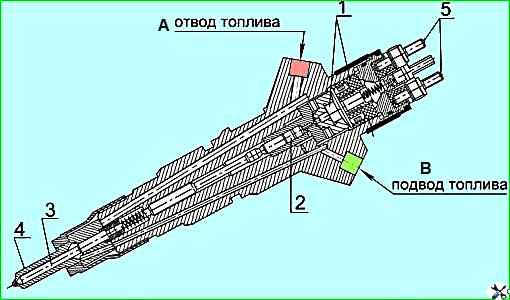
The injector (Figure 1) is designed to inject fuel into the diesel cylinder and ensure high-quality fuel atomization
The diesel engines use CRIN2 injectors manufactured by BOSCH (Germany).
The required injection start time and fuel supply amount are provided by the action of the injector electromagnetic valve.
The injection start time is set by the electronic control system of the diesel engine.
The electronic unit generates injector control signals based on the “reading” of signals generated by the crankshaft speed sensor and the primary shaft of the fuel injection pump drive gearbox, installed in a certain angular position relative to each other.
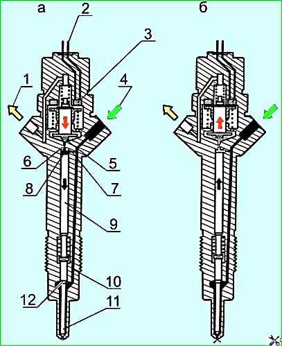
The operating principle of the injector is shown in Figure 2.
Fuel is supplied via the high-pressure line through the supply channel 4 to the injector atomizer 11, as well as through the fuel supply throttle opening 7 - into the chamber of the control piston 8 through the fuel outlet throttle opening, which can be opened by the electromagnetic valve, the chamber is connected to the return drain line 1.
When the throttle opening 6 is closed, the hydraulic force acting from above on the control piston exceeds the fuel pressure force from below on the chamfer (shoulder) 12 of the injector needle.
As a result, the needle is pressed against the nozzle seat and tightly closes the nozzle openings. As a result, the fuel does not enter the combustion chamber.
When the electromagnetic valve 3 is triggered, the electromagnetic anchor moves upward and the ball 5 opens, opening the throttle hole 6.
Accordingly, both the pressure in the control valve chamber and the hydraulic force acting on the control valve piston decrease.
Under the action of fuel pressure on the cone, the atomizer needle moves away from the seat, so that the fuel enters the combustion chamber of the cylinder through the atomizer holes.
The control supply is an additional amount of fuel intended to lift the needle, which after use is diverted to the fuel return line.
In addition to the control feed, there are fuel leaks through the nozzle needle and the guide of the control piston.
All this fuel is diverted into the return line, to which all other units of the injection system are connected, and returns to the fuel tank.
The amount of injected fuel is proportional to the time the electromagnetic valve is turned on and the pressure in the rack, and does not depend on either the engine crankshaft speed or the operating mode of the fuel injection pump (time-controlled injection).
When the electromagnetic valve is de-energized, the anchor is pressed down by the force of the valve locking spring and the valve ball 5 closes the throttle opening.
After the throttle opening of the fuel outlet is closed, the pressure in the control valve chamber again reaches the same value as in battery.
This increased pressure moves the control piston down together with the spray needle.
When the needle fits tightly against the spray seat and closes its holes, injection stops.
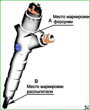
Replacement of the sprayers based on the results of testing the “COMMON RAIL” fuel system should be carried out taking into account the markings of the sprayer and sprayer applied in the places indicated in Figure 3.
Replacing the sprayer in the sprayer without the use of special equipment and specially trained personnel, as well as during the warranty period, is prohibited.
During the warranty period, replacing the sprayer in The nozzle can only be produced at a Bosch service center or specially authorized Bosch workshops.
")

")
")
")
")
")
")
")