Checking the tightening of the cylinder head mounting bolts
Check the tightening of the cylinder head mounting bolts after the break-in period and every 40 thousand km of run on a warmed-up diesel engine in the following order:
- - remove the cap and cylinder head cover;
- - remove the rocker arm shaft with rocker arms and struts;
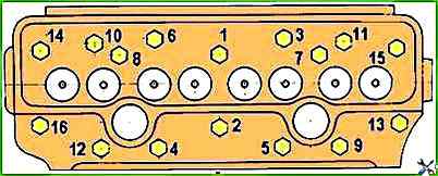
- - use a torque wrench to check the tightening of all cylinder head mounting bolts in the sequence shown in Figure 1, and tighten if necessary.
Tightening torque -220±10 Nm.
After checking the tightening of the cylinder head mounting bolts, reinstall the rocker arm shaft and adjust the clearance between the valves and rocker arms.
Checking the clearance between the valves and rocker arms
Check the clearance between the valves and rocker arms and, if necessary, adjust every 20 thousand km of run, as well as after removing the cylinder head, tightening the cylinder head bolts and when valve knocking occurs.
The clearance between the rocker arm striker and the end of the rod valves when checking on an unheated diesel engine (water and oil temperature no more than 60°C) should be:
- 1) inlet valves - 0.25 mm;
- 2) outlet valves - 0.45 mm.
When adjusting the gap between the end of the valve stem and the rocker arm striker on an unheated diesel engine, set:
- inlet valves - 0.25 mm;
- outlet valves - 0.45 mm.
Adjust in the following order:
- - remove the cylinder head cover cap and check the fastening of the rocker arm axle struts;
- - turn the crankshaft until the valves overlap in the first cylinder (the intake valve of the first cylinder begins to open, and the exhaust valve finishes closing) and adjust the clearances in the fourth, sixth, seventh and eighth valves (counting from the fan), then turn the crankshaft one revolution, setting the overlap in the fourth cylinder, and adjust the clearances in the first, second, third and fifth valves.
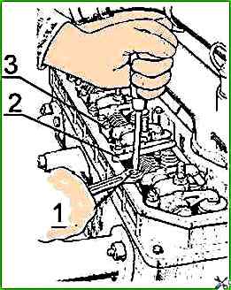
To adjust the clearance, loosen the lock nut of the screw on the rocker arm of the adjustable valve in accordance with Figure 2 and, turning the screw, set the required clearance using the feeler gauge between the rocker arm striker and the end of the valve stem.
After setting the clearance, tighten the lock nut.
After adjusting the clearance in the valves, replace the cylinder head cover cap.
")

")
")
")
")
")
")
")