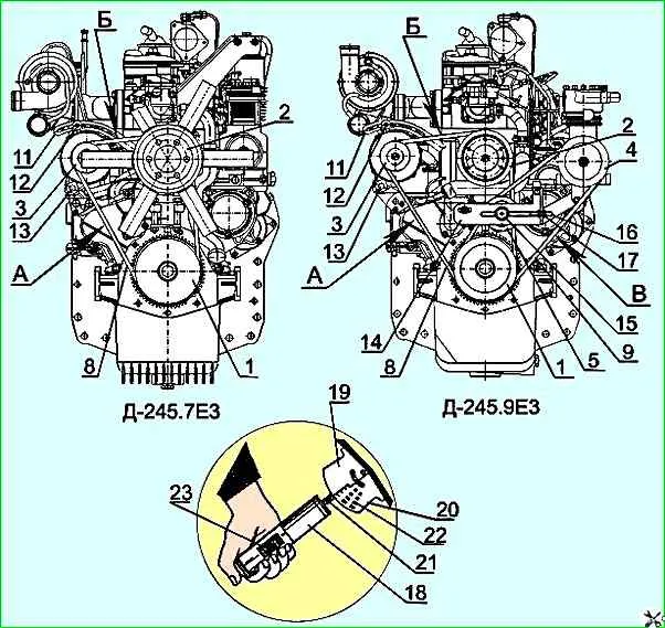
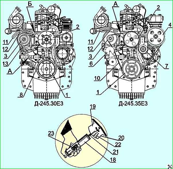
Checking the tension of the generator, water pump, and compressor drive belts D-245E3
Check every 5 thousand km.
Check using the KI-8920 device in the following order:
- - bring the device to its original position, for which set the load indicator 23 (Figure 1(a, b)) to zero with the button and move the movable segments 19 and 20 apart so that their lower ends are at the same level;
- - install the device with segments on the belt being checked in the middle of the span between the pulleys and press the handle-housing 18, watching the reading of the load indicator 23;
- - as soon as the load on the belt reaches the set value (see the table in Figure 1(a, b), remove the device and determine the belt deflection value on the scale 22 applied to the segments;
If the belt deflection does not correspond to the required value specified in the table, adjust its tension.
If the tension is insufficient, the belts slip and wear out quickly, and the diesel engine overheats.
Excessive belt tension leads to their stretching, and also causes accelerated wear of the bearings of the water pump, generator and compressor.

Engine D-245.7E3: A - belt tension control point - belt deflection 15-22 mm with a force of 40±2 N; B - belt tension control point - belt deflection 7-12 mm with a force of 40±2 N
Engine D-245.9E3: A, B - belt tension control point - belt deflection 15-22 mm with a force of 40±2 N; B - belt tension control point - belt deflection 7-12 mm with a force of 40±2 N

D-245.30E3 engine: A - belt tension control point - belt deflection 12-17 mm with a force of 40±2 N; B - belt tension control point - belt deflection 6-10 mm with a force of 40±2 N
Engine D-245.35E3: A - belt tension control point - belt deflection 7.5 mm with a force of 90 N
To adjust the tension of the generator and water pump drive belts on diesel engines D-245.7E3, D-245.9E3, D-245.30E3, loosen the nuts securing bolts 13 of the generator legs and bolt 12 of the generator to the bar 11.
Adjust the belt tension by turning the generator housing.
Tighten the bolt securing the generator to the bar and the nuts of the bolts securing the generator legs.
If one of the belts is worn or damaged, replace them as a set (both belts).
To tension the compressor drive belt on the D-245.9E3 diesel engine, loosen the tension roller fixing nut 15 and lock nuts 17.
Tighten the belt by turning the tension screw 16 by moving the tension roller 5.
Tighten nuts 17 and nut 15.
The poly V-belt of the D-245.35E3 diesel engine is equipped with an automatic tensioner 6 and does not require tension adjustment.


