Connection diagram for fuel level sensor

Fuel level sensor connection diagram
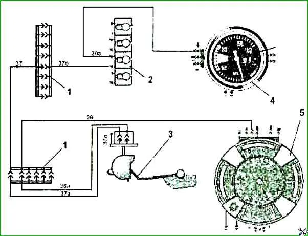
Fig.2 Connection diagram of the fuel level sensor:
1 - connecting block; 2 - indicator of reserve fuel remaining 2202.3803-19; 3 - fuel indicator sensor 5302.3827; 4- tachometer 2541.3813; instrument cluster 36. 3801.
Wire colors: white - 30 f, 30 g; red - 37, 37 a, 37 6; pink-black - 36 a; black: 29 h, 37 d level

new

Parts and kits of nominal and repair sizes of the UAZ-3151 engine Table 1 Part or kit number – Name - Nominal or repair size (diameter), mm

Transmission of torque to the drive axles is carried out by open-type cardan shafts (Fig. 1), each of which has a movable spline connection and two cardan joints