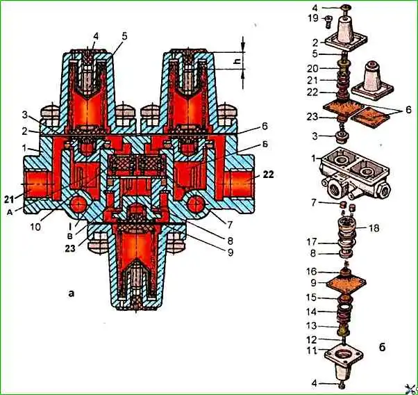
The triple safety valve (Fig. 1) performs the following functions:
- - divides the air line coming from the compressor into two main and one additional circuit;
- - automatically switches off one of the circuits in case of damage or loss of tightness;
- - maintains compressed air pressure in undamaged circuits and ensures their replenishment with air from the compressor;
- - maintains tightness in all undamaged circuits in case of damage or loss of tightness of the supply line;
- - feeds the additional circuit from both main circuits.
Disassembling and assembling the valve
To disassemble the triple safety valve, it must be clamped in a vice with soft jaws by the fastening bosses, loosen screws 19 securing upper protective covers 2, and then, holding them with your hand, unscrew screws 19 and remove one cover and then the other.
If the protective covers do not come off by themselves under the action of springs 21, light tapping on them with a copper or wooden hammer is allowed. The remaining parts of the valves 3 and the membrane 6 are easily removed from the housing

To disassemble the additional circuit valve, housing 1 must be turned 180° in a vice and clamped.
Then unscrew the screws, remove the cover 11 and take out the valve 8 with the spring 14, guide 13, plate 15 and membrane 9.
Check valves 7 are removed from housing 1 after dismantling the thrust ring 17 with special round-nose pliers.
Cracks, hairlines and other defects visible to the eye are not allowed on the surface of the housing parts.
The parts must be cleaned of rust and burnt-on deposits. All rubber parts must be replaced with new ones.
The assembly procedure for the triple safety valve is the reverse of disassembly.
The assembly of valves, rubber sealing rings and other rubber parts must be carried out carefully, preventing their damage.
The presence of scratches, cuts and other defects on the surface of these parts is not allowed.
Before adjustment during assembly, the adjusting screws 5 must be screwed into the covers to a depth of 9 mm from the upper plane of the covers.
Adjustment and testing of the triple safety valve
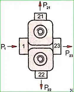
Install the triple safety valve on the test bench and connect according to the diagram shown in (Fig. 2).
Then supply and release air into outlet 1 three times under a pressure of 0.75 MPa.

Adjust the bypass pressure of the main circuits by supplying air under a pressure of 0.56 MPa to outlet 1, then gradually unscrew the adjusting screw 5 (see fig. 1) first in the water circuit until pressure appears in terminal 21, then in the other circuit until pressure appears in terminal 22.
To adjust the pressure in the additional circuit, air must be supplied to terminal 21 or 22 under a pressure of 0.51 MPa and the adjusting screw of the additional circuit must be gradually unscrewed until pressure appears in terminal 23.
After adjusting the triple safety valve, adjusting screws 5 must be fixed with paint and closed with rubber plugs 4.
To check the tightness of the triple safety valve, air must be supplied to terminal 1 under a pressure of 0.75 MPa. the pressure in terminals 21, 22 and 23 should become equal to the pressure in terminal 1.
Bleed air from terminal 1 and the pressure in terminals 21, 22 and 23 should not drop.
Then release air from terminals 21 or 22 and the pressure in terminals 23, 21 or 22 should not drop.
Next, you need to set the pressure to 0.75 MPa again in terminals 1, 21, 22 and 23 and release air from terminal 23, while the pressure in terminals 1, 21 and 22 should not fall below 0.42 MPa.
Check the tightness of the triple safety valve by soaping.


