Liquid heater mod. PZhD8 or PZhD12A, installed on ZIL vehicles and buses, is designed for pre-start heating of the diesel engine at ambient temperatures below minus 15 °C and heating of the bus interior in the cold season.
The heater operates independently of the diesel engine and therefore can operate both when the vehicle is moving and when parked.
The heater is supplied with fuel and electricity from the corresponding systems of the car or bus.
When working with the heater, it is prohibited:
- - igniting the heater when the boiler is not filled with liquid;
- - topping up an overheated boiler with coolant;
- - filling the fuel tank with the heater running;
- - pre-heating the engine with the heater in closed spaces;
- - return the thermal fuse button to the on state after switching off the heater due to overheating without eliminating the cause that caused the overheating.
If a flame or smoke appears at the gas outlet from the flue pipe, turn off the heater and, after it stops, proceed to troubleshooting or adjustment.
The main characteristics of the heaters are given in Table 1.
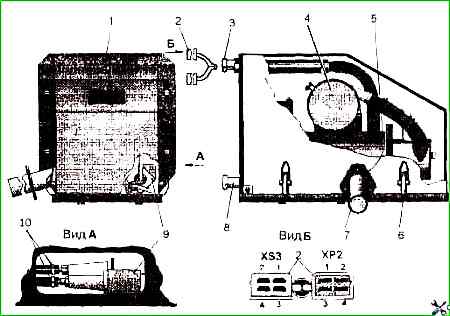
The installation of the heater is shown in Fig. 1, and the device - in Fig. 3.
The heater is mounted in an installation box, which is secured to the frame of a car or bus.
The heater boiler 5, which is covered by a casing 1, is attached to the base of the box with four bolts.
The casing is attached to the base with three latches 6, which provide free access to the boiler if necessary, and is designed to protect the boiler from dirt and moisture.
A window (View A) is provided in the base brace for access to the fuel pump.
Two openings are provided in the base on the side of the liquid pipes for access to the fuel pump mounting screws.
The heater boiler (see Fig. 3) is a heat exchanger 1 with a burner 9, an electromagnetic fuel pump and an air blower 3.
Combustion occurs in the boiler working mixture coming from the burner, and the heat released through the walls of the heat exchanger heats the liquid of the cooling system circulating under the action of the liquid pump.
The heat exchanger is made of four cylinders that form the outer and inner liquid jackets.
The inner jacket forms a direct gas duct, and the space between the inner and outer liquid jackets serves as a return gas duct.
The burner 9 is attached to the front wall of the heat exchanger 1 through a gasket with six bolts.
The working mixture is formed in the burner from the fuel supplied by the electromagnetic fuel pump 9 (see Fig. 1), and air supplied by blower 3 (see Fig. 3) of air through air duct 8, its ignition and combustion.
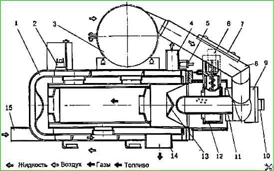
A glow plug 6 and a flame indicator 10, which monitors combustion, are installed in the burner 9.
The part of the burner called the flame swirler 13 enters the heat exchanger, where the main combustion of the fuel occurs.
At the top of the boiler, a tie rod The air blower 3 is attached to the shaft of the electric motor of which an impeller is attached, sucking in and blowing air.
An additional resistor 7 is attached to the air duct 8 of the burner 9 to reduce the rotation speed in partial mode.
Air enters the central part of the flame stabilizer 11 and through a special channel into the spark plug sleeve 6.
Fuel is supplied to the nozzle of the spark plug sleeve 6 and gets onto the linings of the sleeve and the evaporation chamber.
Fuel is supplied by an electromagnetic fuel pump.
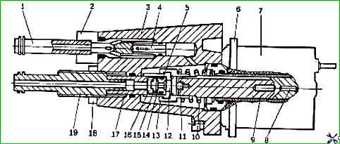
The sleeve 14 (Fig. 2) enters the groove of the hook 13, which fits tightly on the anchor of the electromagnet 9. The suction valve 12 moves freely inside the hook.
Fuel from the tank is supplied to nipple 1, passes, when the pump is running, through the filter mesh 4 and is discharged through the nipple 19.
The electromagnet 7 is attached to the pump body 3 with four screws using the flange 6.
The fuel pump operates as follows.
When voltage is applied to the electromagnet 7, the anchor 9 is pulled in, compressing the spring 10 to the stop 11. Together with the anchor, the catch 13 moves, which in turn pulls the sleeve 14.
A vacuum is created between the sleeve 14 and the plunger 17.
Due to the difference in the end clearances between the suction valve 12 and the sleeve 14, a gap is formed through which the fuel enters the area with reduced pressure.
The discharge valve 15 at this time pressed against the valve seat 5 by the spring 16.
When the voltage supply to the electromagnet is stopped, the anchor 9 together with the catch 13 and the sleeve 14 returns to its original position under the action of the spring 10.
In this case, the suction valve 12 is pressed against the end of the sleeve 14 by the stop of the anchor 11.
The fuel located in the cavity between the sleeve 14 and the plunger 17 passes under pressure into the hole of the valve seat 5, the discharge valve 15 with the spring 16 is pressed and exits through the nipple 19.
To adjust the pump performance, it is necessary to loosen the nut 18 and unscrew or screw in the nipple 19.
When screwing in, the fuel consumption decreases, and when unscrewing it, it increases.
After adjustment, it is necessary to tighten nut 18.
The heater operation control and heater unit fault diagnostics are provided by the electronic control unit (CU) installed behind the instrument panel in the cabin, and the timer (for the PZhD12A heater) in accordance with the electrical circuit.
To control the heater operation, a temperature sensor 5 is installed in the liquid outlet pipe 4 of the boiler (see Fig. 3).
To prevent overheating, there is a thermal fuse 2 in the rear part of the heat exchanger housing, which switches off the heater in case of overheating.
The heater has the following operating modes
Switching on and ignition
When the switch on the instrument panel is turned on, power is supplied to the CU and the indicator lights up (for PZhD8) or the timer indicator shows the indication according to the table. 1 (for PZhD12A).
After completing the initial diagnostics during maintenance, the control unit must switch to ignition mode, in which case the liquid electric pump 14 (see Fig. 3), air blower 16 (to partial mode), spark plug 15 and after 45 s the fuel pump 19 (to partial mode) are switched on.
Indication of the indicator - in accordance with p.- 1 of the table. 1. After 90-180 s, ignition occurs and the light of the combustion flame affects the flame indicator 21, upon the signal of which the control unit 1 switches off the spark plug 15, ensuring the transition of the heater to the "full" mode.
If no signal is received from the flame indicator within 180 s (no ignition), the control unit must stop sending pulses to the fuel pump and repeat the ignition cycle again.
Characteristics of heaters
Heater PZh8
Heat output ±10%, kW (kcal/h):
- - full mode 9.0 (7700);
- - partial mode 4.0 (3500)
Fuel consumption, kg/h not more:
- - full mode 1.1;
- - partial mode 0.4
Fuel - Diesel according to GOST 305-82
Nominal supply voltage, V 12
Power consumption without an electric motor with a pump, W, no more than:
- - full mode 60;
- - partial mode 36
Current consumed by a spark plug, A, no more than 21
Heater PZhD12A
Heat output ±10%, kW (kcal/h):
- - full mode 12.0 (10350)
- - partial mode 5.0 (4300)
Fuel consumption, kg/h, no more than:
- - full mode 1.4
- - partial mode 0.6
Fuel - Diesel according to GOST 305-82
Nominal supply voltage, V 12
Power consumption without an electric motor with a pump, W, no more than:
- - full mode 60
- - partial mode 36
Current consumed by the spark plug, A, no more than 21
If there is no start in the repeated cycle, the control unit must provide an indication of the alarm m in accordance with item 13 of Table 1.
Full mode
When the heater is operating in full mode, the liquid electric pump, air blower, and fuel pump operate.
The glow plug is disabled. The control unit monitors the temperature sensor readings.
When the coolant temperature rises to 90 °C
The control unit must ensure the transition to partial heater operation mode.
Partial mode
When the heater is operating in partial mode, the liquid electric pump, air blower, and fuel pump (in partial mode) operate.
The glow plug is disabled.
The indicator light indicates in accordance with item 2 of Table 1. The control unit monitors the sensor readings.
When the coolant temperature drops to 48°C, the control unit must ensure the heater switches to the "full" mode.
When the coolant temperature rises to 80°C, the control unit must ensure the heater switches to the "cooling" mode.
Cooling mode
When the heater operates in the cooling mode, the liquid electric pump 14 and the air blower 16 operate (in full mode).
The glow plug and fuel pump are turned off.
After 120... 180 s, the control unit must turn off the air blower and monitor the readings of sensor 20.
When the coolant temperature reaches below 48°C, the control unit must ensure the heater switches to the "ignition" mode.
Shutdown mode
When When switching off the heater, press the "WARM-UP" button on the timer (for the PZhD12A heater) or the switch on the control panel (for the PZhD8 heater), after which the indicator goes out.
The control unit switches off the glow plug and the fuel pump. The liquid electric pump and the air blower are switched on (full mode).
The operating time of the liquid electric pump and the air blower is 16 - 120-180 ° C.
After this, the control unit should switch off the liquid electric pump and the air blower. The control unit is completely disconnected from the power supply.
The timer indicator will go out (for the PZhD12A heater).
Combustion is monitored by the flame indicator, and the liquid heating temperature is monitored by the temperature sensor and thermal fuse.
The monitoring consists of the following:
- - if combustion in the heater does not start within 180 s from the moment the fuel supply starts, then the start will be repeated;
- - if the start does not occur in this case, then the heater will automatically turn off;
- - if the flame suddenly goes out during operation, then the start will be repeated. If the start does not occur again within 180 s, then automatic shutdown will occur;
- - if the heater boiler overheats, the thermal fuse is triggered and the heater will switch off;
- - if the voltage increases (15 V) or decreases (10.5 V), automatic shutdown will occur;
- - the heater will not switch on if the spark plug or fuel pump is faulty;
- - the air blower is monitored when switched on and, if it is faulty, the heater will not switch on.
If the control unit detects a malfunction in the heater, it will execute the shutdown program.
Actions in extreme conditions. If the liquid temperature exceeds 103 °C, which is possible if the temperature sensor is faulty, the thermal fuse contacts will open and the heater will turn off.
In this case, it is necessary to determine and eliminate the cause of the defect and only then close the thermal fuse contacts by pressing the button located on its body.
If the heater boiler overheats without coolant, it is necessary to wait until the boiler cools down to the ambient temperature, and only then, having eliminated the cause of the malfunction, fill the boiler with low-freezing liquid.
The heater (We install the heater on the ZIL-5301) manufactured in Tyumen has proven itself well.
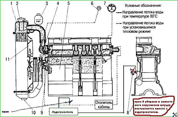
Connect the heater inlet via a fitting instead of a drain cock.
Connect the heater outlet via a tee, cutting the supply hose to the heater.
Also install a tap near the tee, you can install a heater tap from a VAZ-2109 car.
We install the tap so that when the heater is turned off and during operation diesel block this liquid path.
Otherwise the heater will heat poorly.
You must not forget to turn this tap on and off in time.
As the operation of this heater at t = -20° C has shown, 30-40 minutes is enough to start the diesel normally.
")

")
")
")
")
")
")
")