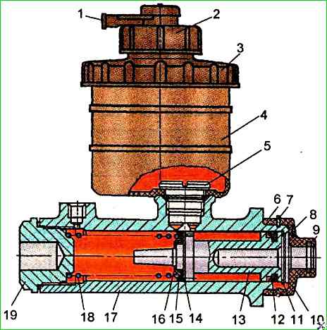
Master brake cylinder of the drive, divided by axles
Master brake cylinders (MBC) are connected by two studs into one unit with pneumatic chambers, which are pneumatic boosters, and are mounted on brackets on the front panel of the cabin under the hood of the car for braking the wheels of the front axle and behind the rear axle for the wheels of the rear axle.
The main causes of the MBC failure are wear or loss of elasticity of the rubber cuff, wear of the working surfaces of the cylinder and piston, clogging of the compensation hole.
To disassemble the brake master cylinder, perform the following operations:
- - disconnect the terminal connection of the wires from the brake fluid level sensor on the brake master cylinder reservoir cover;
- - disconnect the hose from the pneumatic chamber from the brake master cylinder;
- - dismantle the brake master cylinder together with the pneumatic chamber from the bracket,
- - unscrew the two nuts that secure them, disconnect the brake master cylinder from the pneumatic chamber;
- - clean and rinse the brake master cylinder surface from dirt, mineral oils and other contaminants;
- - unscrew the cover 3 of the reservoir together with the sensor and drain the brake fluid;
- - place the brake master cylinder with the reservoir down and, by pressing piston 13 (Fig. 1) several times, remove the remaining brake fluid from cylinder;
- - secure the master brake cylinder in a vice with soft jaws;
- - remove the reservoir from the cylinder by unscrewing the nipple 5 of its fastening;
- - dismantle the coupling sleeve 10 and remove the thrust ring 11 using special pliers, holding the piston 13 from falling out;
- - remove the piston from the housing 17 of the master cylinder by hand.
After disassembling, rinse all parts with clean brake fluid and inspect them carefully.
It is strictly forbidden to get mineral oils, gasoline, kerosene or diesel fuel on the parts, since even traces of these liquids on the parts can lead to the destruction of the rubber cuffs in the assembled cylinder.
The working surface of the master brake cylinder and piston must not have any rust, marks and other irregularities.
To eliminate defects on the "mirror" of the brake master cylinder, it is allowed to hone it.
If there are defects that cause a significant increase in the diameter of the "mirror", the brake master cylinder housing must be replaced.
Each time the brake master cylinder is disassembled, it is necessary to check the elasticity of the spring 18 and replace all the rubber cuffs, even if they still appear to be in good condition.
To assemble the brake master cylinder, the following operations must be performed:
- - assemble piston 13, installing new rubber cuffs 12 and 15;
- - secure the brake master cylinder housing in a vice with soft jaws;
- - generously lubricate the “mirror” of the main brake cylinder and the piston with cuffs with fresh, clean brake fluid, install spring 18 in crankcase 17;
- - direct piston 13 as an assembly into the crankcase, pressing spring 18 until it stops. When the working edges of the cuffs pass through the groove under the thrust ring, the working edges of the cuffs must be pressed down with a blunt wooden object;
- - having sunk the piston into the cylinder, install the thrust ring 1.1 using special pliers;
- - lubricate the working surface of the cylinder to a depth of approximately 15 mm with a thin layer of DT-1 anti-corrosion grease;
- - install the coupling 10 on the master cylinder housing;
Test the master cylinder for leaks using the following method.
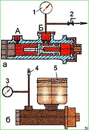
With terminal "A" open (Fig. 2), move the piston by about 20 mm, then plug terminal "A" and apply a vacuum of 0.0635±0.0035 MPa to terminal "B";
- turn off the vacuum source with tap 2.
The vacuum value should not change for at least 5 s or move the piston by about 20 mm and fix it.
Supply compressed air under a pressure of 0.15+0.02 MPa to terminal "A", and connect a pressure gauge to hole "B". No pressure drop is allowed within 5±1 s;
- install tank 4 (see Fig. 1) on the master cylinder crankcase and secure it with nipple 5;
Fill the reservoir with Neva brake fluid and bleed. Create a pressure of 0.3±0.03 MPa and fix the rod.
The pressure should not drop by more than 0.02 MPa for at least 5 s.
Release the piston, while the pressure should drop to zero. Press on the piston, creating a pressure of 14+1.4 MPa.
Fix the rod.
The pressure should not change for at least 10 s. There should be no traces of brake fluid on the surface of the brake master cylinder;
- - install the brake master cylinder together with the air chamber on the bracket on the bus and secure them with nuts;
- - connect a hose to the brake master cylinder and a tube to the air chamber; fill the brake drive hydraulic system with fresh brake fluid;
- - tighten the tank caps together with the brake fluid level sensors;
- - connect the terminal connections of the wires to the brake fluid level sensors on the tank caps of the master cylinder;
- - bleed the brake hydraulic drive and check the operation of the master cylinder, as described above.
The main brake cylinder of the drive, separated by the sides
From operating experience: - if possible, it is best to throw out this cylinder and put two single-tank cylinders, it will be cheaper and much more reliable than this cylinder.
This cylinder is a continuous headache on the bull.
The main brake cylinder is connected by two studs into one unit with a two-cavity brake chamber, which is a pneumatic booster, and is mounted on a bracket on front panel of the cabin under the hood of the car.
The main causes of the master brake cylinder failure are wear or loss of elasticity of the rubber seals, wear of the working surfaces of the cylinder and pistons, clogging of the compensation holes.
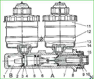
To disassemble the brake master cylinder, perform the following operations (Fig. 3):
- - disconnect the terminal connections of the wires from the brake fluid level sensors on the brake master cylinder reservoir caps;
- - disconnect all the tubes from the brake master cylinder, and the hoses (tubes) from the dual-cavity brake chamber;
- - dismantle the brake master cylinder together with the dual-cavity brake chamber from the bracket by unscrewing the two nuts securing them; disconnect the brake master cylinder from the dual-cavity brake chamber;
- - clean and wash the brake master cylinder surface from dirt, mineral oils and other contaminants;
- - unscrew the tank caps together with the sensors and drain the brake fluid;
- - place the brake master cylinder with the tanks down and, pressing the primary chamber piston "A" several times, remove the remaining brake fluid from the cylinder;
- - secure the brake master cylinder in a vice with soft jaws;
- - remove the tanks from the cylinder by unscrewing the nipples 13 of their fastening;
- - dismantle the cover and remove the thrust ring 15 using special pliers, holding pistons 5 and 7 from falling out;
- - remove the pistons from the master cylinder by hand.
You can also use compressed air, supplying it to the master cylinder boss in chamber "B".
In this case, one of the holes in this chamber must be plugged.
After disassembling, all parts must be washed with clean brake fluid and carefully inspected.
The working surface of the master brake cylinder and pistons must not have rust, scratches or other irregularities.
To eliminate defects on the "mirror" of the brake master cylinder, it is allowed to hone it.
If there are defects that cause a significant increase in the diameter of the "mirror", the brake master cylinder body must be replaced.
Each time the brake master cylinder is disassembled, the elasticity of the piston springs must be checked and all rubber seals must be replaced, even if they still appear to be in good condition.
To assemble the brake master cylinder, the following operations must be performed:
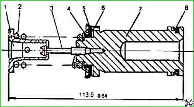
- - assemble primary piston 7 in accordance with Fig. 4 with spring 2 (in case of its disassembly), having installed new rubber seals 5 and 8:
- - install new rubber seals 3 and 6 (see Fig. 3) on the secondary piston;
- - secure the master cylinder housing in a vice with soft jaws:
- - generously lubricate the “mirror” of the brake cylinder and pistons with cuffs with fresh, clean brake fluid.
- - when passing the working edges of the cuffs through the groove for the thrust ring, the working edges of the cuffs must be pressed down with a blunt wooden object;
- - having sunk the pistons into the cylinder, install the thrust ring 15 using special pliers;
- - install the guide 10 on the brake master cylinder housing;
- - install the tanks 11 on the brake master cylinder housing and secure them with fittings 13 and bracket 12;
- - install the brake master cylinder together with the two-cavity brake chamber on the car bracket and secure them with nuts;
- - connect all the tubes to the brake master cylinder, and the hoses to the two-cavity brake chamber;
- - fill in fresh brake fluid into hydraulic brake drive system;
- - tighten the reservoir caps together with the brake fluid level sensors;
- - connect the terminal connections of the wires to the brake fluid level sensors on the reservoir caps of the master brake cylinder;
- - bleed the hydraulic brake drive and check the operation of the master brake cylinder, as described above.
Hydraulic drive pressure regulator
The hydraulic drive pressure regulator on vehicles with a drive split along the sides is designed to adjust the brake fluid pressure when braking the vehicle in order to prevent locking of the rear wheels when the vehicle is partially loaded.
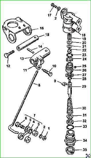
The device of the hydraulic drive pressure regulator is shown in Fig. 5.
The regulator is secured to the vehicle frame side member and reacts to the load perceived by the vehicle's rear axle with the load rod 8.
To remove the regulator from the vehicle, disconnect the lower hinge of strut 4 from the bracket on the rear suspension cross member by unscrewing the nut, removing the spring washer and removing the lower hinge axle from the hole in the bracket.
Disconnect the pipes and remove the regulator by unscrewing the two bolts securing the regulator to the bracket on the rear suspension cross member.
To disassemble the pressure regulator, perform the following operations:
- - secure the pressure regulator in a vice with soft jaws by housing 18;
- - unscrew bolt 12, remove thrust pin 14 and release the end of load rod 8.
")

")
")
")
")
")
")
")