The hydraulic drive pressure regulator on vehicles with a split drive on the sides is designed to adjust the brake fluid pressure when braking the vehicle in order to prevent the rear wheels from locking when the vehicle is partially loaded
The regulator is attached to the vehicle frame side member and reacts to the load perceived by the vehicle's rear axle with the load rod 8.
To remove the regulator from the vehicle, disconnect the lower hinge of the strut 4 from the bracket on the rear suspension cross member, for which it is necessary to unscrew the nut, remove the spring washer and remove the lower hinge axis from the hole in the bracket.
Disconnect the pipes and remove the regulator by unscrewing the two bolts securing the regulator to the bracket on the rear suspension cross member.
To disassemble the pressure regulator, perform the following operations:
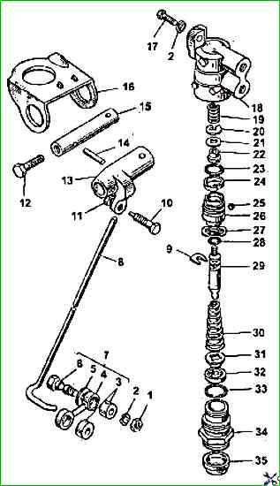
- - secure the pressure regulator in a vice with soft jaws by the housing 18;
- - unscrew bolt 12, remove thrust pin 14 and release the end of the loading rod 8;
- - remove axle 15 and remove pressure lever 13;
- - remove protective cover 35; unscrew sleeve 34 securing the pressure regulator housing; remove return spring 30 and washer 27;
- - pull piston 29 with sleeve out of housing 18 by the tailstock; remove pressure spring 24 from sleeve 26 and remove ball 25 from sleeve seat; to remove cone 22, remove bracket 9 and remove piston from sleeve.
ATTENTION!
Remove piston from sleeve only if defective parts included in this unit are to be replaced. and also when replacing the piston cuff
If the ball valve is not tight enough, use light hammer blows through the mandrel to calibrate the socket in the sleeve.
The hydraulic drive pressure regulator must be assembled in the reverse order, replacing defective parts and all rubber seals.
Before assembly, all parts of the pressure regulator must be generously lubricated with fresh brake fluid.
The operation of the assembled pressure regulator must be checked on a special stand.
The fluid pressure at the outlet of the regulator installed on the stand should be approximately half the pressure at the inlet with the adjusting rod in the lower position.
Keeping the supplied pressure at a certain level, smoothly raise the loading rod 8.
The outlet pressure should increase, which indicates proper operation regulator.
The pressure regulator should be checked only with fresh brake fluid.
The checked regulator is installed on the vehicle in the reverse order of its dismantling.
After installing the regulator on the vehicle, it is necessary to bleed the hydraulic drive and adjust it on the vehicle.
To check the regulator, perform the following operations:
- - install the vehicle on the horizontal part of the overpass or inspection pit;
- - loosen lock nut 11 of adjusting bolt 10; by rotating the adjusting bolt 10, set a gap of 0.1 mm between the spherical end of the bolt and the piston 29 of the regulator.
The gap size is checked visually, while the loading rod and the parts of the pressure lever must not be touched.
The presence of a visually observable gap between the spherical part of the bolt and the piston is a sufficient condition for continuing the adjustment;
- - screw the adjusting bolt 10 into the pressure lever 13 by two turns;
- - hold the adjusting bolt 10 from turning, tighten the lock nut 11;
After adjusting the regulator, it is necessary to carry out a control test of the car without a load on a dry horizontal section of the road with asphalt or concrete pavement and, if necessary, correct the adjustment.
Braking must be carried out from a speed of 50-60 km/h, gradually increasing the force on the brake pedal until the wheels of one of the axles lock.
If during braking the rear wheels lock ahead of time, then, holding the adjusting bolt 10 from turning, unscrew the lock nut 11 and turn turn the adjusting bolt 180° counterclockwise, tightening it with a lock nut and not allowing it to rotate.
After this, you need to conduct a test drive.
If the rear wheels lock too late, adjusting bolt 10 should be turned clockwise.
From operating experience: If this unit fails, it is best to remove it, connect all the pipes directly and not get hung up on it.
")

")
")
")
")
")
")
")