Design of the D-245 diesel engine
The D-245 diesel engine and its modifications are a four-stroke piston four-cylinder internal combustion engine with an in-line vertical arrangement of cylinders, direct injection of diesel fuel and compression ignition.
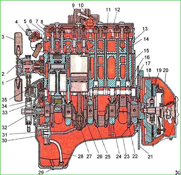
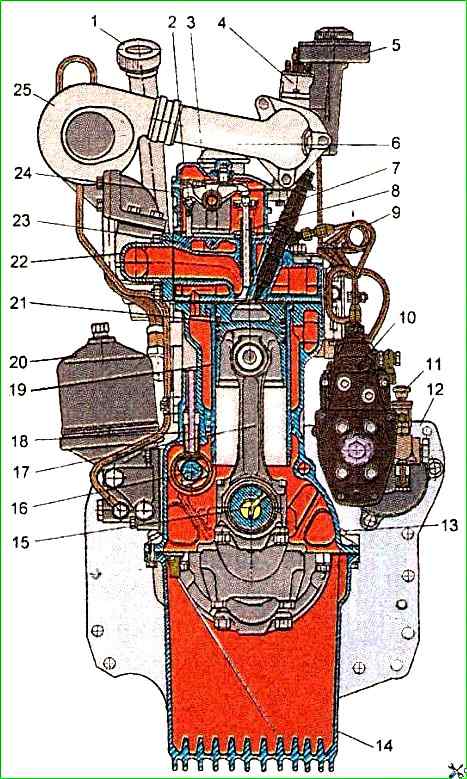
The main assembly units of the diesel engine are: cylinder block, cylinder head, pistons, connecting rods, crankshaft and flywheel.
To ensure high technical and economic performance of the diesel engine, turbocharging with intermediate cooling of the charge air is used in the intake system.
The use of a turbocharger with adjustable boost pressure in the boost device allows the diesel engine to have improved throttle response, provided by increased torque values at low crankshaft speeds.
Technical characteristics of the D-245.12 diesel engine
Diesel type - Four-stroke turbocharged diesel engine
Method of mixture formation - Direct fuel injection
Number of cylinders - 4
Cylinder arrangement - In-line, vertical
Firing order of cylinders 1 - 3 - 4 - 2
Cylinder diameter - 110 mm
Piston stroke 125 mm
Cylinder displacement - 4.75 l
Direction of crankshaft rotation - Right
Compression ratio (calculated) - 15.1
Rated power kW (hp) 80 (108.8)
Rated speed 2400 min -1
Maximum torque 350 Nm
Speed at maximum torque, min -1 1300-1700
Minimum stable speed at idle, min -1, no more than 800±50
Specific fuel consumption by external speed characteristic g/kW-h:
- - minimum – 218;
- - at rated power - 245
Hourly fuel consumption at rated power - 19.6 kg/h
Hourly fuel consumption at minimum stable idle speed, kg/h, no more than - 1.5
Nominal fuel injection advance angle, deg. to TDC - 19 ±1
Total oil consumption (including replacement) as a percentage of fuel consumption, no more than - 1.3
Oil consumption for burnout according to GOST 18509-88 as a percentage of fuel consumption, no more than - 0.5
Oil pressure in the main oil line at nominal diesel operating mode - 0.25-0.35 MPa
Dry diesel weight - 500 kg
Overall dimensions mm - 1011.5x702.0x1080.5
The cylinder block is the main body part of the diesel engine and is a rigid cast iron casting.
Four removable liners made of special cast iron are installed in the vertical bores of the block.
The liners are installed in the cylinder block along two centering belts: upper and lower.
In the upper belt, the liners are secured with a flange, in the lower belt, they are sealed with two rubber rings located in the grooves of the cylinder block.
Coolant circulates between the walls of the cylinder block and the liners.
The end walls and transverse partitions of the cylinder block have lugs in the lower part, designed to form crankshaft supports. The caps are installed on these bosses.
The bosses and caps form the beds for the main bearings.
The beds for the main bearing shells are bored from one installation assembled with the main bearing caps, so the caps cannot be interchanged.
The cylinder block has a longitudinal oil channel, from which oil flows through transverse channels to the crankshaft main bearings and camshaft bearings.
The design of the diesel cylinder block provides for five camshaft bearings.
In the upper part of the second and fourth crankshaft supports, nozzles are installed, which serve to cool the pistons with a stream of oil.
On the outer surfaces of the cylinder block there are machined mating surfaces for fastening the oil filter, water pump, coarse and fine fuel filters, distribution shield and rear sheet.
The cylinder head is a cast iron casting, in the internal cavities of which there are inlet and outlet channels closed by valves. Inlet ports - with a screw profile
To ensure heat dissipation, the cylinder head has internal cavities in which the coolant circulates.
The cylinder head has insert valve seats made of heat-resistant and wear-resistant alloy
The struts, rocker shaft with rockers, head cover, intake manifold and cover cap covering the valve mechanism are installed on top of the cylinder head
On the left side (from the fuel pump side) four injectors are installed in the head, and on the right side the exhaust manifold is attached to the head
To seal the connector between the head and the cylinder block, a gasket made of asbestos-free fabric reinforced with perforated steel sheet is installed
The holes in the gasket for the cylinder liners are edged with sheet steel.
When When assembling a diesel engine at the factory, the cylinder holes of the gasket are additionally edged with fluoroplastic split rings.
Crank mechanism
The main parts of the crank mechanism are: the crankshaft, pistons with piston rings and pins, connecting rods, main and connecting rod bearings, and a flywheel.
The crankshaft is made of steel and has five main and four connecting rod journals.
The axial force of the crankshaft is supported by four bimetallic half rings or half rings made of aluminum alloy, installed in the bores of the cylinder block and the cover of the fifth main bearing.
To reduce the loads on the main bearings from inertial forces, counterweights are installed on the first, fourth, fifth and eighth cheeks of the crankshaft.
The crankshaft is sealed with cuffs at the front and rear.
The timing gear (crankshaft gear), oil pump drive gear, water pump and generator drive pulley are installed on the front end of the shaft. The flywheel is attached to the rear flange of the shaft.
The piston is made of aluminum alloy. The combustion chamber is made in the piston bottom. The combustion chamber is offset relative to the piston axis.
The piston has three grooves in the upper part - the compression rings are installed in the first two, and the oil scraper ring in the third.
A special cast iron insert is poured under the groove of the upper compression ring. The piston bosses have bored holes for the piston pin.
The piston rings are made of cast iron. The upper compression ring is made of high-strength cast iron and has an isosceles trapezoid in cross-section.
The second compression ring is conical. On the end surface near the lock, the compression rings are marked "Top" ("TOP"). The oil scraper ring is box-type with a spring expander.
The piston pin is hollow, made of chromium-nickel steel. The axial movement of the pin in the piston bosses is limited by retaining rings.
Connecting rod - steel, I-section. A bushing is pressed into its upper head. There are holes in the upper head of the connecting rod and the bushing for lubricating the piston pin.
The boring of the bed in the lower head of the connecting rod for the liners is carried out in assembly with the cover. Therefore, changing the connecting rod covers is not allowed.
The connecting rod and cover have the same numbers stamped on their surfaces. In addition, the connecting rods have weight groups by the weight of the upper and lower heads.
The designation of the weight group is applied to the end surface of the upper head of the connecting rod. The diesel engine must be equipped with connecting rods of the same group.
The liners of the main and connecting rod bearings of the crankshaft are made of bimetallic strip.
The diesel engines use liners of the main and connecting rod bearings of two sizes in accordance with the nominal value of the crankshaft journals.
Four repairs are also provided for the diesel engine repair sized liners.
The flywheel is made of cast iron and is attached to the crankshaft flange with bolts. A steel toothed ring is pressed onto the flywheel.
The distribution mechanism consists of a camshaft, intake and exhaust valves, as well as their installation and drive parts: tappets, rods, rocker arms, adjusting screws with nuts, plates with crackers, springs, struts and a rocker shaft.
The camshaft is a five-bearing one, driven by the crankshaft through the distribution gears.
The camshaft bearings are five bushings pressed into the block bores.
The front bushing (on the fan side) made of aluminum alloy has a thrust collar that holds the camshaft from axial movement, the remaining bushings are made of special cast iron.
The tappets are steel. The working surface of the tappet plate is welded with chilled cast iron and has a spherical surface of a large radius (750 mm).
As a result of the fact that the camshaft cams are made with a slight inclination, the tappets perform a rotational motion during operation.
The tappet rods are made of steel rod. The spherical part entering the tappet and the rod cup are hardened.
The valve rocker arms are steel, swing on an axis mounted on four racks. The outer racks are of increased rigidity.
The rocker arm axis is hollow, has eight radial holes for supplying oil to the rocker arms. The movement of the rocker arms along the axis is limited by spacer springs.
The intake and exhaust valves are made of heat-resistant steel. They move in guide bushings pressed into the cylinder head.
Each valve closes under the action of two springs: external and internal, which act on the valve through the plate and crackers.
Sealing cuffs installed on the valve guide bushings prevent oil from entering the diesel cylinders and exhaust manifold through the gaps between the valve stems and the guide bushings.