To disconnect the rear axle without springs, the car must be placed on a flat horizontal platform or on an inspection ditch equipped with a lifting device
Removing the rear axle
Remove the shock absorbers by unscrewing the lower and upper fasteners.
To avoid leakage of brake fluid from the system, it is allowed to clamp the hoses supplying brake fluid to the bridge using a clamp.
This should be done carefully so as not to damage the hoses, and then disconnect the hoses from the bridge.
Disconnect the driveshaft.
Release the parking brake cable by removing the rollers.
Unscrew the bolts securing the brake force regulator bracket to the bridge.
Unscrew the nut securing the stabilizer pin to the bracket and use a copper drift to knock the pin out of the bracket.
Using a lifting mechanism, lift the rear of the car so that the rear springs are freed from the load. Place supports under the axle gearbox.
Evenly unscrew the nuts of the stepladders securing the springs and raise the frame.
Roll out the rear axle from under the frame, supporting it by the gearbox.
Lower the frame onto the stands.
Disassembling the rear axle gearbox
To disassemble the rear axle, you must perform the following operations
Remove the wheels, clean the bridge from dirt.
Drain the oil.
Remove the axle shafts (see “Adjusting the preload of the differential bearings and checking the lateral clearance in the meshing of the final drive gears”).
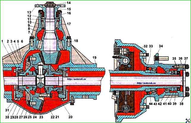
Unscrew the lock nut 39 (see Fig. 1), remove the locking ring.
There are two threaded holes in the locking ring, just like in the axle flange, designed to facilitate their removal.
Unscrew the adjusting nut.
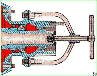
In Fig. Figure 2 shows the removal of wheel hubs using a puller installed with a ring grip on the wheel studs and secured with wheel nuts.
Unscrew the bolts securing the rear axle housing cover and remove it.
Mark with a core the relative position of the bearing caps of the differential cups and the axle housing.
Unlock and unscrew the bolts securing the bearing caps. Remove the covers.
Mark and remove both adjusting nuts, remove the differential along with the bearings
Unscrew the bolts securing the drive gear bearing housing, and then remove it. Remove adjusting shims 18 (see Fig. 1).
Disassemble the glass, article - "Contact adjustment in ZIL-5301 gears"
Press the outer ring of the rear bearing out of the glass using a mandrel.
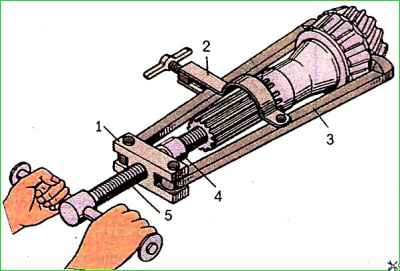
It is recommended to remove the rear bearing from the drive gear shaft using a 20P-7984 puller (Fig. 3).
Unlock and unscrew the driven gear mounting bolts and remove it from the left differential cup using a copper mandrel and a hammer.
Mark the relative position of the differential cups with a core.
Unscrew the bolts securing the differential cups.
Remove the right cup and the right axle gear with the support washer.
Use a thin bit to push the pins of the satellite pins into the pin hole until they stop.
After this, you can press out the pins of the satellites with a punch in any order and remove the satellites with support washers.
Remove the left axle gear from the support washers oh.
The bearing puller from the neck of the differential cup is similar in design to the bearing puller from the drive gear shaft.
In this case, the puller is installed so that the jaws of the puller fit the end of the inner ring of the bearing.
")

")
")
")
")
")
")
")