The design of the front wheel service brakes is shown in Figure 1
Repair of the vehicle service brakes
Disassembling the service brakes involves removing the wheels and hubs with brake discs.
To remove the brake discs from the wheel hubs, unscrew bolts 1.
Before disassembling the floating brake caliper, it must be thoroughly cleaned of dirt and washed, and the clamp must be removed from it. 21 hose fasteners.
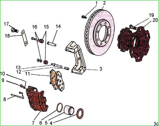
Then you need to put a rubber hose on the bleed valve 10 and lower its end into a clean container.
Unscrew the bleed valve one turn and, pressing on the body 11 of the bracket, push the cylinder pistons into the body. In this case, some brake fluid will flow into the vessel.
To dismantle the brake pads, remove the pin 8 from the retaining pin 7 and pull out the pin.
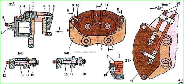
Then, holding the upper guide pin 13 from turning with a special key, unscrew the bolt 15 that secures it to the axle housing, protecting the rubber boot 14 of the pin from damage.
Lift (turn) the housing of the caliper 11 relative to the second pin 17 until it stops in the caliper and remove the brake pads 6.
Unscrew the nut 18 securing the auxiliary pin 17 and remove the housing of the caliper 11.
Remove the dust covers 5 of the piston and carefully, so as not to damage the surface, push the pistons 3 out of the cylinders, using compressed air for this.
Remove sealing rings 4 from the grooves without damaging the inner surface of the cylinders.
Clean and wash the brake mechanism parts with ethyl hydrolysis alcohol. The pistons should be washed especially thoroughly with alcohol.
Using other liquids for washing is prohibited.
Without wiping the parts, let them dry in the air, laying them on clean glossy paper that does not leave lint.
Check the condition of all parts of the service brake.
If the working surface of the piston is damaged or has traces of corrosion, the piston should be replaced.
If the surface of the cylinder is damaged, the caliper housing should be replaced.
The surface of the brake discs should be smooth.
Scratches and small burrs that appear after normal operation of the brakes are not a defective feature, but a disc with severe burrs should be replaced.
If it is impossible to replace the disc, it is allowed to grind it together with the hub.
Grinding should be performed by qualified personnel on special equipment.
The ground surfaces of the disc must have a deviation from flatness of no more than 0.04 mm and from parallelism of no more than 0.04 mm and have a roughness of 0.8 μm.
The runout of the disc relative to the mounting surfaces of the hub must not exceed 0.1 mm.
There must be no sharp edge on the inner circumference of the ground surface.
Both sides of the disc must be ground to the same value, but the total thinning of the disc must not exceed 3 mm.
Before assembling the brake caliper, do the following:
Lubricate the working surfaces of the cylinders and pistons with unused brake fluid.
Install new sealing rings 6 in the grooves of the cylinders of the caliper body 7.
Lubricate with a thin layer of grease DT-1 cylinder surface to the groove.
Carefully, so as not to damage the polished surface, insert pistons 5 into the cylinders with the open end facing outward.
Put the edges of the new protective covers 15 on pistons 5. Lubricate the pistons in the area of the covers with DT-1 grease.
Put the free edges of the protective covers on the cylinders.
By inspection, determine the condition of the ie pins 13 and 14, on the surface of which there should be no scratches, noticeable signs of wear or damage to the thread, damaged pins must be replaced.
Remove bushing 16 of the auxiliary pin.
Clean the pins and the holes for them in the calipers, and rinse them with alcohol. Install the body of the caliper 11 on the caliper 1.
Put a new bushing 16 on the auxiliary pin 17.
Lubricate the working surfaces of the pins with Molikot-Si 7439 or TSIA-TIM-221 grease and insert the pins into the holes of the caliper 1.
Install new protective pin covers 14 and tighten the guide pin mounting bolt 13 and the nut 18 of the auxiliary pin, protecting the protective covers from damage: Install the clamp 21 of the brake hoses 20 on the caliper.
After this, install the brake caliper on the front axle steering knuckle and secure it as described in the articles, - Assembling the front axle of the ZIL-5301
Fasten the brake hoses in the bracket, as shown in Fig. 3, preventing them from twisting, and connect to the pipelines.
Install the brake pads 6 and secure them with pin 7. Install the pin 8.
Bleed the brake system on the car by performing the following operations, and keeping in mind that the hydraulic drive has two independent circuits.
Fill the brake system with Neva brake fluid according to TU 6-01-1163-78.
Fill the pneumatic drive with compressed air.
Press the brake pedal several times.
Add fluid to the tanks to the norm.
Remove the protective cap of the bleed valve and put a rubber or plastic hose on the head of the bleed valve of the rear left wheel cylinder.
Lower the free end of the hose into a transparent container partially filled with brake fluid.
Unscrew the bleed valve one turn, smoothly press the brake pedal until it stops and screw the valve in with a little force.
Release the pedal. This operation should be repeated at intervals of several seconds until brake fluid without air bubbles flows from the hose lowered into the vessel.
At the same time, it is necessary to monitor the fluid level in the master cylinder tanks and refill them as needed, without allowing the level to fall below the lower belts of the tanks.
After the air bubbles stop appearing, tighten the bleed valve with the brake pedal pressed.
In the same way, bleed the rear right brake and both front brake mechanisms.
After removing the hose from the bleed valves, carefully wipe the valve and put protective caps on their heads.
When bleeding the hydraulic drive, a pressure difference arises in its circuits, displacing the piston of the signal device, as a result of which the signal lamp lights up.
To return the signal device to its original position, unscrew the 1/2 turn the bleed valve, having first removed the protective cap from it, and, smoothly pressing the brake pedal, make sure that the lamp goes out.
Then, holding the pedal in the pressed position, tighten the valve.
In case of replacing a set of front or rear brake pads, as well as at least one brake disc, it is necessary to run in the pads to the discs using the following method:
- - make thirty moderate-intensity braking from a speed of 90 km / h to 30 km / h with an interval of at least two kilometers between braking;
- - make three effective braking on the verge of locking the wheels from a speed of 80 km / h to a complete stop with a minimum interval between braking.
After replacing and running in the pads, it is necessary to check the action of the brakes in road conditions.
Rear brake mechanisms wheels
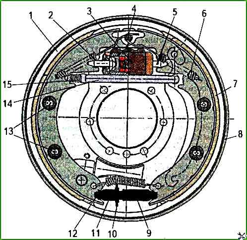
The rear wheel brake mechanisms are shoe-type, drum-type.
To disassemble the rear wheel brake mechanism, clean the brake drum from dirt and make sure it rotates freely.
The parking brake system must be in the released state.
Unscrew the six bolts securing the brake drum to the rear wheel hub and remove it by turning it so that the protrusions on the drum align with the grooves on the hub.
To remove the shoes, use a wire remove springs 2 and 6 from support pin 4 using a loop or hook; disassemble rods 13 securing shoes to brake shield 8 by pressing in the upper cup and turning it until the groove in the cup matches the position of the rod, remove tension spring 12.
Disconnect release lever 14 of the parking brake and spring 15 from the shoes.
After disassembling the brake mechanism, all parts must be washed with cleaning solution MS-6 or MS-8 TU 6-12-978-76, blown with compressed air and carry out defect detection
Inspect the inner working surface of the drum and check the thickness of the linings on the primary 1 and secondary 7 shoes.
Cracks and chips on brake parts are not allowed. Thread damage is allowed to no more than two threads.
Brake lining wear is allowed to a level of 1.5 mm to the rivet heads.
If brake parts wear beyond the permissible dimensions, the worn parts must be replaced.
It is recommended to correct the bending of the brake shield by straightening. If the bending is greater, the shields must be replaced.
When assembling the rear wheel brake mechanism, all operations must be performed in the reverse order of disassembly. In this case, keep the following in mind.
The positions of the secondary and primary brake shoes and shoe springs must not be interchanged.
The primary brake shoe differs from the secondary shoe in that it has a larger number of turns and a smaller wire diameter.
When installing the tension spring 12 (see Fig. 3) and the adjusting screw 10, the nut 9 must be tightened to the limit to compensate for the thickness of the new linings.
If only one brake shoe on the rear wheels is worn out, all four rear brake shoes must be replaced.
During assembly, the bearing surfaces of the bushings and axles must be lubricated with a thin layer of grease.
Gluing new linings to the brake shoes. If necessary, you can replace the brake linings on the shoes by gluing new ones.
To ensure reliable gluing of the friction linings to the brake shoes, the following conditions must be met.
Glue with glue grade VS-10T GOST 22345-77 or TIIM-4 TU 38.114513-96 from JSC NIIDTI (Yaroslavl).
Before gluing the linings, the brake shoes must be cleaned by mechanical processing from traces of old linings, provided that the geometric shape is preserved according to the drawing.
After mechanical processing of the shoes, contamination of the prepared surface with dust, oil and other substances that weaken the adhesive bond is not allowed.
On the inner surface of the linings, the glossy layer must be removed while maintaining the geometric dimensions products.
Irregularities, cracks, traces of oil and contamination of the surface are not allowed.
A uniform layer of glue is applied with a brush to the clean, degreased surfaces of the pads and linings at the rate of 1.5-2 g per 100 cm 2 area.
After applying the glue, the parts must be dried in the air for at least 15 minutes and no more than 90 minutes at a temperature of at least 15 °C. It is not allowed to touch the surface coated with glue with your hands.
The parts must be glued together in a special device that ensures the correct relative position of the pad and the shoe block and with the pad pressed against the shoe block with a force of 49-78 N/cm 2.
The parts must be glued together in a drying oven at a temperature of 180 °C for 120 minutes, excluding the time it takes to heat the oven to the specified temperature.
After gluing the pads, the product must be checked for cracks, chips, distortion, the absence of a gap between the pad and the shoe block, and compliance with the drawing.
The strength of the adhesive joint must comply with GOST R ISO 6312-93. The breaking force must be at least 100 N/cm 2.
Adjusting the service brakes
As the friction linings wear out, it is necessary to adjust the gap between the shoe lining and the drum every 4,000 km.
To adjust, do the following:
- - turn off the parking brake;
- - raise the rear wheels;
- - remove the spring plugs from the rear brake shields;
-
- through the hole in the brake shield, use a special spatula 1 (or a wide screwdriver) to rotate the sprocket of the adjusting screw 2 (on the left brake from the bottom up; on the right - in the opposite direction), spreading the shoes until the wheel is braked (does not turn by hand). Rotate the sprocket in the opposite direction to ensure free rotation of the wheel, insert the spring plugs.
From operating experience: The hole for the pads in the brake shield is very small, and it is very inconvenient to adjust. When changing pads or during other repairs associated with providing access to this hole, it is necessary to widen it. This can be done with electric welding or a grinder. It is advisable to weld additional suitable pieces of iron onto the expansion lever, because a common defect is the jumping off of this lever. And also Replace the brake shoe mounting rods with suitable bolts and two nuts. The brake shoe spring can be easily removed with pliers; the long end of the spring can be bent without fear, because this long end is not hardened. It is advisable to install an intermittent buzzer on the handbrake to prevent starting on the handbrake. Because of this, the rear shoes often "fly out" of their places.
")

")
")
")
")
")
")
")