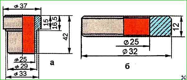
Press the bushings using a special mandrel (see Fig. 1) into the holes of the steering knuckle flush with the surface so that the open ends of the grooves on the bushings are facing the inside of the knuckle (the pressing force must be at least 10 kN)
Pressed-in bushings must not protrude above the ends of the sealing cuffs to avoid undercutting them.
The lubrication holes in the bushings must match the oiler holes in the fists.
Iron the bushings to a size of at least 29.55 mm, ensuring their alignment.
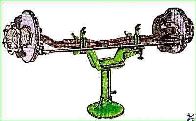
Install the front axle beam on the stand shown in Fig. 2.
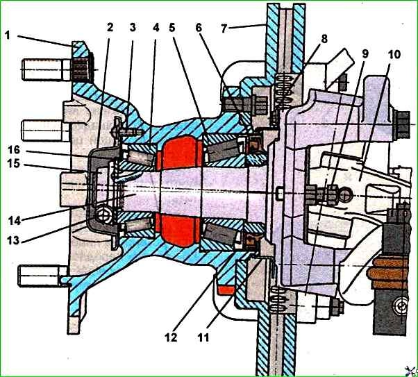
Insert the sealing rings into the steering knuckle sockets, and the thrust ball bearing into the lower socket, pre- lubricating it with Litol-24 grease, and in the upper socket - adjusting linings 8 (Fig. 3).
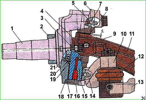
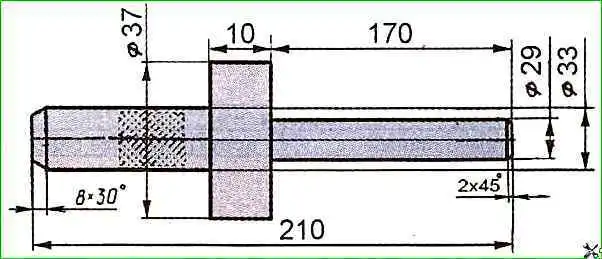
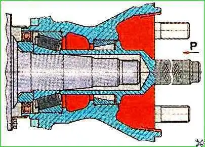
Install steering knuckle 1 and connect it to the axle beam by inserting a special mandrel from below into the holes in the knuckle and beam (Fig. 4).
Check the gap "C" between the upper support of the steering knuckle and the upper plane of the beam support (see Fig. 3). The gap should be no more than 0.2 mm.
If necessary, adjust the gap with shims 8. The total number of shims should not exceed two.
Press in the kingpin from above, having previously lubricated it and the bushings with engine oil.
Press in the kingpin so that the chamfer on it coincides with the hole in the beam boss for the wedge.
Secure the kingpin with wedge 9, screw a nut and washer onto it. The tightening torque of the nut should be 28 - 36 Nm.
Install the kingpin caps with sealing rings and secure them with thrust rings 18.
Screw the grease nipples into the holes in the steering knuckles and lubricate the kingpin bushings and bearing with Litol-24 grease until the grease comes out of the gaps of the mating parts.
The rotation of the knuckles relative to the beam by hand should be smooth and without jamming at an angle of no more than 45°.
Fasten the lower arms on the right and left steering knuckles, and the upper arm on the left knuckle. The tightening torque of the arm mounting bolts is 160 - 200 Nm.
Assemble the transverse steering rod and install it on the lower steering arms, secure the ball pins with nuts and cotter pin them. Tightening torque of lever mounting bolts - 160 - 200 Nm.
Assemble the longitudinal steering rod and install it in place, secure the pin with a nut and cotter pin it.
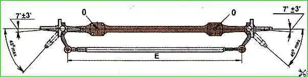
If you have a special device, adjust the angle (4'-10') of the steering knuckle installation (wheel alignment) relative to the 0 - 0 axis (Fig. 5) by changing the dimension "E", which is achieved by rotating the transverse steering rod.
Install mud shield 11 (see Fig. 6) and secure it with bolts 8 and spring washers.
Lubricate the inner bearing generously with grease, insert it into the hub, install washer 12 and press the seal using a special mandrel.
If the outer rings of the steering knuckle bearings are worn, they must be replaced.
The rings are fitted into the hub with interference fit; for the inner bearing - 0.010-0.059 mm, for the outer bearing - 0.009-0.059 mm.
Install the hub assembly with the brake disc onto the steering knuckle with. using a special mandrel (Fig. 7), while the mandrel should rest against the inner ring of the bearing.
Lubricate the outer bearing generously with grease and install it on the journal using a special mandrel, while the mandrel should rest against the inner ring of the bearing.
Install the thrust washer 16, screw on the adjusting nut 15 (see Fig. 6) and tighten it to a torque of 60-80 Nm, turning the wheel hub in both directions so that the bearing rollers are installed correctly.
Axial clearance is not allowed, the hub should not rotate after tightening.
Then unscrew the adjusting nut by approximately 45° and tighten the clamping bolt 13 of the clamping connection of the adjusting nut 15 to a torque of 16-18 Nm.
With this adjustment, the axial clearance in the hub bearings will be about 0.2 mm.
In operation, if the axial clearance is checked with an indicator head, the clearance should be within 0.125-0.25 mm.
Install cover 2 with a gasket and tighten the three screws 3 for securing the cover.
Install the caliper with the hose bracket on the brake disc, install the locking plate and tighten the two caliper mounting bolts.
Bend the brake caliper mounting locking plate.
When installing the front axle on the car, you need to lift the front part of the car frame with a lift and roll the front axle.
Lower the frame slightly onto the suspension.
Attach the front axle to the frame vehicle.
Lower the front of the vehicle and remove the lifting devices.
Then perform the operations of installing the front axle on the vehicle, the reverse of disassembly.
If the toe-in and steering angles of the wheels were not checked during assembly of the front axle, they should be checked and adjusted if necessary.
")

")
")
")
")
")
")
")