After repairing the crankshaft, as well as the flywheel, clutch or pulley installed on it, they must be balanced
Dynamic balancing of parts installed on the crankshaft (flywheel, pulley, crankshaft, pressure and driven clutch disks) must be carried out on machines of the MS-970 or PBM-4 model.
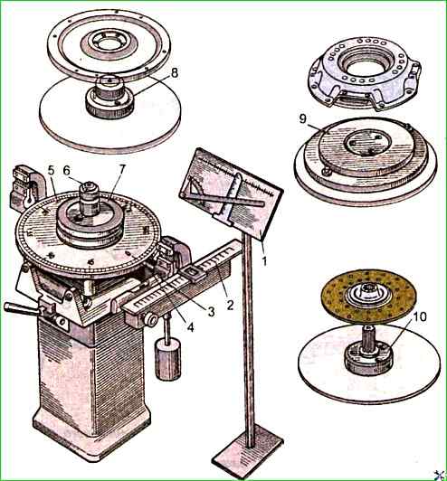
Less accurate static balancing of these parts is performed on machines of the model. 40U-314 (Fig. 1).
Balancing of the crankshaft, as well as the crankshaft with the flywheel and clutch installed on it, should be carried out in dynamic mode with weights on the connecting rod journals, replacing the connecting rod-piston group on the connecting rod journal.
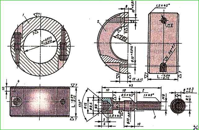
The balancing weight (Fig. 2) consists of two identical half rings connected by two bolts made of 40x steel (GOST 4543-71), with a hardness of 35-40 HRCэ.
The outer, inner surfaces of certain diameters and the ends of the weight are finally processed after connecting the half rings with bolts.
The inner diameter of the weight is D+0.025 mm, where D is the diameter of the crank pin.
The offset of the bolt axes relative to the ends and the inner diameter of the weight should be no more than 0.05 mm.
The bolts must be of the same mass.
The weight is adjusted by mass by reducing the outer diameter with an accuracy of +1 g and is balanced statically on a mandrel with an accuracy of 2 g/cm so that the center of gravity of the load is on the axis of the load and in the middle of its width.
After this, risks are applied to the outer surface to ensure the assembly of the half rings in one position.
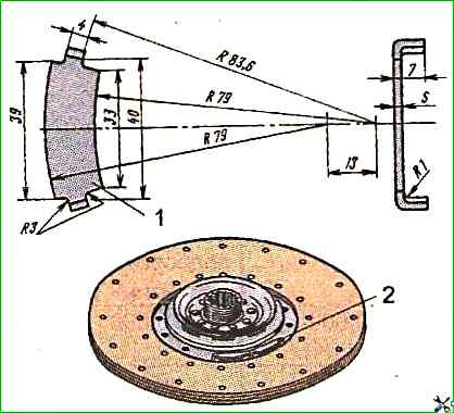
The clutch driven disc assembly is balanced relative to the side surfaces of the hub splines by installing one to three weights (Fig. 3), which are attached to the disc with antennae.
After bending them, the immobility of the connection is ensured. Residual imbalance is no more than 25 g/cm.
The balancing weights are made of 08 sheet steel with a thickness of 2.0 mm and a weight of 12 g; 1.2 mm thick and weighing 7.5 g.
The clutch pressure plate with the housing assembly is balanced relative to the working surface of the pressure plate and two diametrically located holes for fastening the housing to the flywheel, by drilling holes with a diameter of 13.8 mm in the bosses under the springs to a depth of no more than 23 mm.
The distance between the supporting surfaces of the disk and the housing should be 9.84-0.1 mm with a tolerance of non-parallelism of these surfaces of 0.03 mm.
The residual imbalance should be no more than 50 g cm.
After balancing, the installation holes are marked. With any repeated installation using the same holes, the imbalance should be no more than 90 g cm.
The crankshaft with the flywheel and clutch assembly is balanced relative to the outer main journals by drilling holes with a diameter of 15 mm (to a depth of no more than 15 mm, with a distance between them of at least 5 mm) at a distance of 184 mm from the shaft axis in segments of the flywheel working surface not covered by the clutch casing or when drilling holes in the bosses under the springs of the clutch pressure plate.
The residual imbalance on the clutch (flywheel) side should be no more than 70 g/cm.
Before balancing, a weight is placed on each crank pin, and the driven clutch disk is centered relative to the inner diameter of the bearing on the crankshaft flange using the primary shaft of the gearbox or a special mandrel.
")

")
")
")
")
")
")
")