Installing the ZIL-5301 valve timing mechanism
The valve timing shield gasket must not have any visible damage
Nots and other mechanical damage to the machined surfaces of the 4 valve timing shield are not allowed
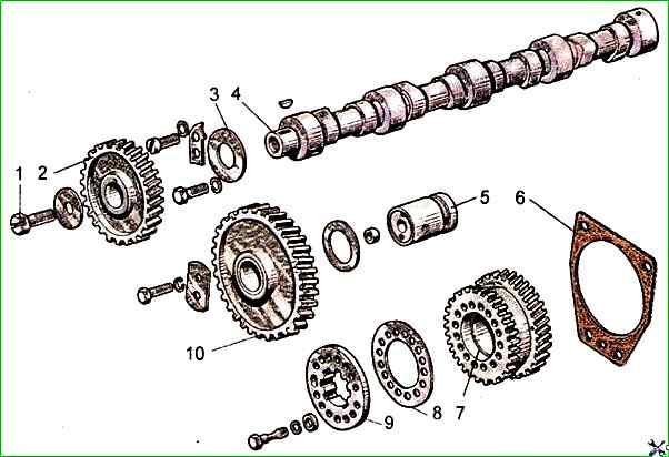
No nicks or dents are allowed on the timing gear teeth, cams and camshaft journals.
The camshaft bushings in the cylinder block and the camshaft journals must be wiped with a clean cloth.
The camshaft journals must be lubricated with engine oil.
The longitudinal play of the camshaft must be within 0.3-1.04 mm; The shaft should rotate freely, without jamming.
Before installation, the tappets should be wiped and lubricated with engine oil.
The tappets should move freely in the holes in the block under manual force.
The intermediate gear pin should be wiped with a napkin and lubricated with engine oil.
When installing the timing gear and fuel pump drive gears, the corresponding marks on the toothed rims of the gear wheels must match (Fig. 3).
After securing the intermediate gear, the lateral clearance between the teeth of the timing gear wheels must be within 0.1-0.3 mm.
The end clearance between the hub of the intermediate gear wheel and the thrust washer must be within 0.10-0.78 mm.
")

")
")
")
")
")
")
")