ZIL-5301 control output valve
The control output valve (Fig. 1) is designed to check the pressure using control and measuring devices, as well as to select compressed air
The valves are installed in all circuits of the pneumatic brake drive.
Hoses with union nuts or measuring devices with an M16x1.5 connecting internal thread must be used to connect to the valve.
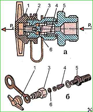
To disassemble the control output valve, clamp it in a vice by nipple 5 and unscrew the protective cap 1.
Unscrew housing 3, take out spring 4 and remove valve 6.
Assemble the valve in the reverse order.
To check the valve's operability, install it on a test bench and connect it according to the diagram shown in Fig. 1a.
Apply air under pressure of 0.75 MPa to terminal 1 (P1) and push and release the valve pusher three times.
Check the valve for leaks.
Then connect a 0.5 liter container to terminal 1 (P2).
Push the valve pusher.
The pressure in terminals 1 and 11 should equalize within no more than 5 seconds.
")

")
")
")
")
")
")
")