Wheel speed sensor and ABS electronic unit ZIL-5301
Wheel speed sensors are designed to determine the angular velocity of the wheels and transmit a signal to the ABS electronic unit
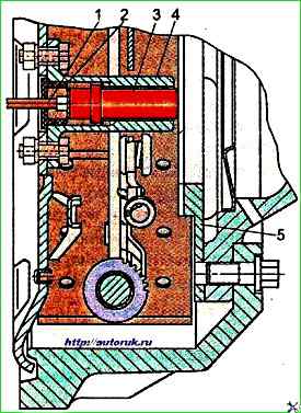
The installation of sensors and exciters is shown in Fig. 1.
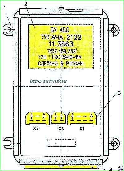
The electronic unit is designed to control the ABS and is installed inside the cabin on the inner instrument panel to the left of the instrument cluster.
The top view of the electronic unit is shown in Fig. 3.
The sensor and the electronic control unit are complex, non-disassemblable devices and cannot be repaired.
If they fail, they must be replaced as an assembly.
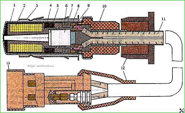
The sensor design is shown in Fig. 3.
The electrical circuit for connecting the ABS devices is shown in Fig. 4
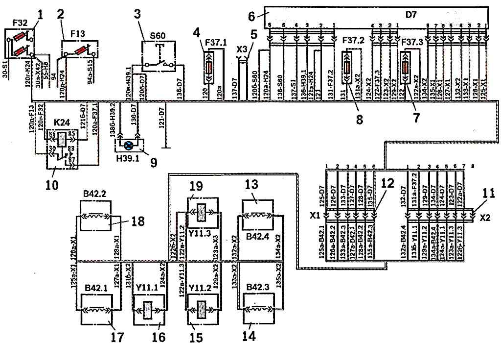
ABS Additional Electrical Equipment Circuit Diagram: 1 - push-button thermal bimetallic fuse 1302.22 for 7.5x2; 2 - push-button thermal bimetallic fuse 10A 29.3722; 3 - control button 11.3704-01; 4 - fuse 164 PR 119 5; 5 - control unit 12.3863; 6 - ABS control unit 112863; 7 and 8 - fuses 6A PR 119-01; 9 - malfunction indicator, ABS PD 20-D; 10 - ABS power relay 111.3747; 11 and 12 - plug connectors; 13 and 14 - wheel sensors of the right and left wheels, respectively, of the rear axle; 15 and 19 - electromagnets of the modulators, respectively, of the left and right wheels of the rear axle; 16 - electromagnet of the wheel modulator of the front axle; 17 and 18 - wheel sensors of the left and right wheels, respectively, of the front axle. Wire color: white - 133,133 A, 135 135 A; blue - 132,132 a, 134,134 a; yellow - 120 d. 131,131 a, 131 b; green - 120 d., 124,124 a, 137; red - 120,120 a, 120 6,120 b, 129,129 a; brown - 126,126 ,128,128 a, 138; orange - 123,123 a; pink - 122,122 a, 122 b,122 b; violet - 125,125 a,127,127 a,136; black - 121,121 a
Fig. 4. ABS additional electrical equipment diagram
")

")
")
")
")
")
")
")