The brake force regulator (Fig. 1) automatically regulates the pressure of compressed air supplied to the brake chambers of the rear wheels during braking in accordance with the current axial load
Disassembly and assembly of the brake force regulator is carried out as follows.
Secure the brake force regulator by the housing 8 (Fig. 1) in a vice with soft jaws with the cap 17 facing up.
Unscrew the screws 15 and remove the connecting tube 1 together with the valve 3 of the atmospheric outlet.
Then unscrew the bolts 16, remove the guide cap 17 and remove the lower piston.
Unscrew the bolts 18 and remove the lower housing 2 together with the shaft 4 of the lever.
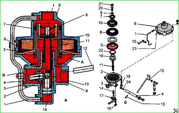
Then remove piston 10 with membrane 5 and insert 6 from upper housing 8. Remove cuff 7 from piston, being careful not to damage it.
When installing a new cuff on the piston, it must be oriented with the edge down.
To remove valve 9, use round-nose pliers to remove thrust ring 21 and then remove the piston with spring and spring plate.
Then remove pusher 11 from lower housing 2, for which shaft 4 should be turned by lever 12 to the extreme upper position, and piston guide 19, for removal of which it is necessary to dismantle thrust ring 22 with round-nose pliers.
Disassembly of shaft 4 of the lever is carried out in case of emergency.
To do this, heat the gas burner screw 24 to a temperature of 200 °C, and then, after cooling, unscrew it from shaft 4.
Then remove ball joint 13 and shaft 4.
When assembling this unit, screw 24 must be placed on anaerobic sealant.
After disassembling, the brake force regulator parts must be washed with clean gasoline or acetone, dried and carefully inspected.
Cracks, hairlines and other defects visible to the eye are not allowed on the surface of the body parts.
The parts must be cleaned of rust and burnt-on deposits. All rubber parts must be replaced with new ones.
Before assembly, the brake force regulator parts must be lubricated with a thin layer of TSIA-TIM-221 grease.
The brake force regulator assembly procedure is the reverse of disassembly.
The valves, rubber sealing rings and other rubber parts must be assembled carefully, preventing damage.
The presence of scratches, cuts and other defects on the surface of these parts is not allowed.
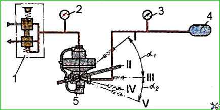
To adjust and check the brake force regulator, it must be installed on the test bench and connected according to the diagram shown in Fig. 2.
Then check the movement of the device lever several times without pressure and with a pressure of 0.7 MPa on the pressure gauge 2.
The lever should move easily, without jamming, from stop to stop by a value of a1 = 35±5° and a2 = 21±4°.
Set the pressure to 0.7 MPa on the pressure gauge 2 and, moving the lever towards the full load, set the pressure on the pressure gauge to 0.6 MPa.
Then move the lever by 4° of the device, towards the "full load" position.
In this case, the pressure on the pressure gauge 3 should become 0.68-0.7 MPa.
This corresponds to the "full load" lever position.
Move the lever from the "full load" position by 15° to the "middle position", then by 30° to the "no load" position and then to the stop.
In these positions, the pressure on the pressure gauge 3 should correspond to the following values:
- - in the "full load" position - 0.68 ÷ 070 MPa;
- - "middle position" - 0.315 ÷ 0.390 MPa;
- - "no load" - 016-0.22 MPa;
- - "no load stop" - over 0.14 MPa.
The pressure on the pressure gauge 2 at all positions of the lever is 0.7 MPa.
A slow decrease in pressure on the pressure gauge 2 to 0 MPa should cause a decrease in pressure to 0 MPa and on the pressure gauge 3 in each of the specified positions of the lever.
The beginning of the increase in pressure I on pressure gauge 3 should occur when the pressure on pressure gauge 2 increases to 0.02 MPa in the "full load" lever position and 0.05 MPa in the "no load" lever position.
With a smooth increase and decrease in pressure on pressure gauge 2, the step change in pressure on pressure gauge 3 in all lever positions should not exceed 0.02 MPa.
ATTENTION!
The movement of the device lever during the test must be carried out with the pressure of pressure gauge 2 equal to zero.
The elastic element of the brake force regulator protects the regulator from damage when the bridge is moved above the limit of the permissible travel of the regulator lever.
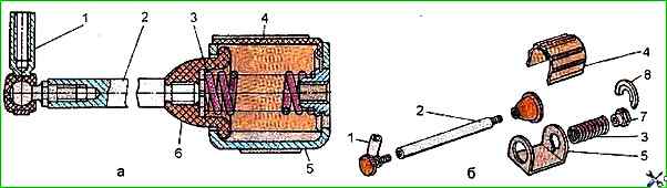
To disassemble the elastic element, clamp it in a vice with soft jaws by the housing 5 and screw the M10x1.5 bolt into the guide 7 (Fig. 3) of the spring.
Pressing on the screwed-in bolt, remove the cap 4 and pin 8, inserting the guide 7 of the spring behind the housing 5.
Then remove the spring 3, the guide 7 of the spring and the rod 2.
The elastic element is assembled in the reverse order.
During assembly, pay attention to the correct installation of the pin 8, which should be installed with the stamping towards the housing 5.
")

")
")
")
")
")
")
")