Features of the design of the single safety valve ZIL-5301
The single safety valve (Fig. 1) serves to protect the vehicle's brake drive from loss of compressed air in the event of damage to the connecting lines, compressed air consumers that are not related to the brake system
When the pressure in the pneumatic drive (for example, the pneumatic-hydraulic booster of the clutch drive as a result of a violation of its tightness) drops to a certain value, the safety valve disconnects the vehicle's brake system and consumers.
To disassemble the valve, place it in a vice with soft jaws and clamp it by the body 8.
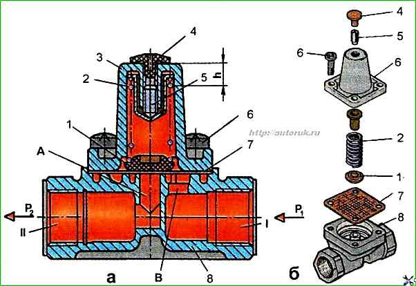
Remove protective cap 4 and unscrew adjusting screw 5, loosening spring 2.
Unscrew screws 6, holding cover 3 with your hand, and remove it together with spring 2 and membrane 7.
After disassembling, the parts of the single safety valve must be washed with clean gasoline or acetone, dried and carefully inspected.
Cracks, hairlines and other defects visible to the eye are not allowed on the surface of the body parts.
The parts must be cleaned of rust and burnt-on deposits. All rubber parts must be replaced.
Before assembling, the valve parts must be lubricated by hand with a thin layer of TSIA-TIM-221 grease, GOST 9433-60.
Assemble the valve in the reverse order.
Assemble the valve, rubber sealing rings and other rubber parts carefully, avoiding damage.
The presence of scratches, cuts and other defects on the surface of these parts is not allowed.
During assembly, screw the adjusting screw 5 into the cover to a depth of 14 mm from the surface of the end of the cover and, if using a new spring 2, hold the valve in this loaded position for 12-24 hours.
To adjust the valve, place it on a test bench and connect it according to the diagram shown in Fig. 1a.
Apply air under pressure 0.55 MPa in port I and gradually unscrew screw 5 until pressure appears in port II.
Feed and release air under a pressure of 0.75 MPa into port I three times.
Gradually increase the pressure in port I.
When port I reaches a pressure of 0.53-0.55 MPa, pressure should appear in port II, and with a further increase in pressure in port I, the pressure in port II should be equal to the pressure in port 1.
Adjust the valve if necessary.
When screwing the adjusting screw 5 into the cover, the bypass pressure increases, and when unscrewing it, it decreases.
After adjustment, the screw must be fixed with paint.
Check the valve for leaks.
When soaping, the appearance of air bubbles is not allowed for 1 min.
")

")
")
")
")
")
")
")