The quick release valve is designed to reduce the actuation time of the parking brake by accelerating the release of air from the energy accumulator by reducing the path traveled by compressed air and increasing the flow area during release
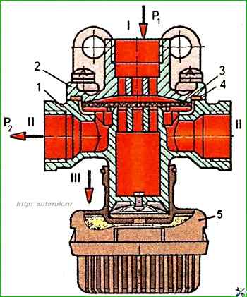
Possible malfunctions of the quick release valve include: compressed air leakage through the connector of cover 2 (Fig. 1) and body 1, which occurs due to loosening of the cover fastening or a defect in the sealing ring 4, and the release of compressed air into the environment from the "III" terminal due to a malfunction of the membrane 3.
To disassemble the quick release valve, unscrew the four screws securing cover 2.
When replacing membrane 3, rubber sealing ring 4 must also be replaced at the same time.
After assembling the valve, it must be installed on the stand and tested for operability and tightness according to the diagram shown in Fig. 1 (close the right terminal "II" with a plug), according to the following method.
Three times supply and release air under a pressure of 0.75 MPa into terminal "I".
Set the pressure in terminal 1 to 0.02 MPa.
In this case, pressure should appear in terminal "II".
Increase the pressure in terminal 1 to 0.75 MPa.
In this case, the pressure in terminal "II" should increase.
The difference between the pressures in terminals "I" and "II" should not exceed 0.02 MPa.
The valve must be checked for tightness under a pressure of 0.5 MPa in terminal "I".
When soaping, the appearance of air bubbles is not allowed for 1 min.
Then it is necessary to set the pressure to 075 MPa in terminals "I" and "II" and successively reduce the pressure in terminal "I".
In this case, a corresponding decrease in pressure should be observed in terminal "II", and air should come out of the atmospheric terminal "III".
When the pressure in terminal "I" decreases to zero, the pressure in terminal "II" should become equal to zero.
")

")
")
")
")
")
")
")