Disassembling the ZIL-5301 steering cardan shaft
The steering cardan shaft wears very little and should be disassembled only in case of mechanical damage to individual parts
Disassembling the steering cardan shaft joints with a crosspiece mounted on needle bearings (Fig. 1) should be done in the same way as the joints of the vehicle cardan shafts.
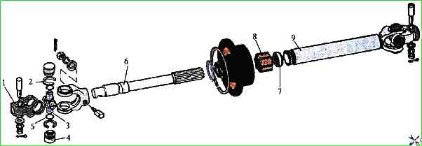
To disassemble the splined connection, unscrew nut 8 and remove splined shaft 6 from splined sleeve 9. Remove seal 7 from shaft 6.
Steering column disassembly
Install the steering column assembly on a workbench and secure it in a vice, holding it by bracket 8 (Fig. 2).
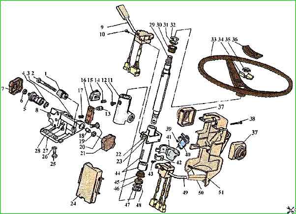
Remove the protective covers 37 of the switches and leave them hanging on the switch handles.
Unscrew the screws 38 securing the halves of the casing and remove them, having first removed the cover with the instrument and starter switch.
Insert the key into the instrument and starter switch 40 and, turning it, open the locking device.
Unscrew the bolt 43 securing the clamp 42 of the housing 41 of the locking device and remove the housing from the column together with the instrument and starter switch.
If replacement is necessary, drill out the three screws 39 securing the instrument and starter switch in the housing and, pressing the latch on the lock, remove the instrument and starter switch from the housing 41.
Unscrew the screws 10 securing the turn signal and light switch and the windshield wiper switch to bracket of the column pipe 44, holding nuts 22 from turning, and remove the switches.
Using flywheels 7 and 21, loosen the column height and tilt adjustment mechanisms.
Holding the flywheel by hand, loosen nuts 6 and 19, unscrew and remove flywheel 7, 21 and nuts 6, 19 and remove lock sleeve 18.
Unscrew column stopper 12 and screw 27 with washer 28 and remove pipe 44 as an assembly.
Clamp the pipe horizontally in a vice and unlock washer 48 by bending its antennae to release nut 47.
Unscrew nut 47, remove lock washer 48 and seal collar 46 as an assembly. When unscrewing the nut, secure the shaft.
Remove the thrust 32 and expansion 31 rings.
Press out shaft 29 from column pipe 44 together with bearing 45.
Press out bearing 30 from the pipe and remove the pipe from the vice. Clamp the column bracket 8 in a vice and remove the thrust ring 3.
Remove the column axle 5 from the bracket in assembly with the adjusting screw 2 and clamp 1, simultaneously remove the spring 14, remove the sector 15.
Remove the column housing 11.
If necessary, unscrew the stoppers 13, remove the rack 16 and spring 17.
After replacement, punch the stoppers 13. Before installation, lubricate the rack with solid oil GOST 4366-76.
Remove the thrust ring 4, remove the adjusting screw 2 in assembly with clamp 1 from the column axle 5 and unscrew the screw from the clamp.
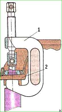
The steering wheel is removed using the puller mod 804.30.000-10 (Fig. 3) or the puller mod. 2495 in the following sequence:
Unscrew nut 35 (see Fig. 2), install the puller on the column, then, turning the handle, press the steering wheel.
Wash the steering column parts and blow them with compressed air.
Wash in MS-6 or MS-8 cleaning solution.