ZIL-5301 Centrifugal Oil Filter
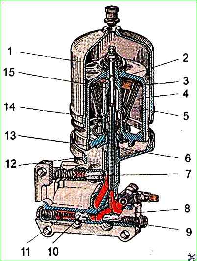
The design of the centrifugal oil filter is shown in Fig. 1
Washing the parts of the centrifugal oil filter made of aluminum alloy in an aggressive environment is not allowed
When assembling the centrifuge, use parts that are free of contamination.
The non-flatness of the mating surface of the filter housing must not exceed 0.08 mm along the entire length.
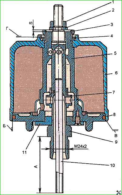
On the surfaces of the openings of the housing 5 (Fig. 2) of the rotor and the cover 11, mating with the journals of the rotor axis 9, traces of chemical destruction are not allowed.
There must be no damage to the threads on the rotor housing 5.
Surface "G" of the annular groove in the rotor cup under the thrust ring 4 must not have any damage.
Non-flatness and non-parallelism of the side surfaces of the thrust ring must not exceed 0.1 mm.
On surface "5" of the rotor housing mating with the cup 6 of the rotor, nicks and dents are not allowed.
Non-roundness and tolerance of the longitudinal section profile of the housing opening. rotor under the upper neck of the rotor axis - 0.01 mm.
The rotor body must be statically balanced.
Residual imbalance - no more than 150 g-mm.
The mass must be corrected by drilling holes in the end of the rotor flange with a diameter of 6 mm to a depth of no more than 2 mm.
The cylindrical surface of the cup, mating with the surface "B" of the rotor, must not have bends and nicks. The non-roundness of this surface is 0.2 mm.
Surface "B" of the internal chamfer of the end of cup 6 of the rotor must not have nicks with sharp edges. The nicks must be cleaned.
The rotor cup is dynamically balanced.
The mass must be corrected in two planes: on the upper end and on the thickening of the lower surface with a depth of no more than 2 mm.
Residual imbalance no more than 50 mm.
The non-roundness and tolerance of the longitudinal section profile of the hole in the cover 11 of the rotor housing for the lower journal is 0.01 mm.
Cracks are not allowed on the oil filter housing.
The depth of the pressure reducing valve seat in the filter housing must not exceed 52 mm.
The depth of the drain valve seat and the seat of the centrifugal filter valve must not exceed 72 mm at the housing.
The curvature of the generatrix of the drain valve spring and the centrifugal filter valve, freely lying on plate, should not exceed 1 mm.
The curvature of the generatrix of the pressure reducing valve spring, lying freely on the plate, should not exceed 1 mm.
The cover 11 of the rotor housing, installed on the rotor axis, should rotate freely under manual force.
Before installing the cover, the lower neck of the rotor axis should be lubricated with engine oil.
Narcs, dents, cracks and deformation of the nozzle 7 are not allowed.
Tube 10 should have a tight fit in the rotor axis and protrude, providing dimension "A" equal to 70±0.5 mm.
Bending of tube 10 is not allowed.
The runout of the outer surface of the end of the pressed tube relative to the average diameter of the M24x2 thread of the rotor axis should not exceed 0.3 mm.
Before installing the cover and rotor housing, the axle journals must be lubricated with engine oil.
The rotor axle must first be blown out with compressed air.
The special nut 3 of the assembled rotor cup must rotate freely with manual force.
Before installing the rotor cup 6 on the rotor housing, the rubber sealing ring must be lubricated with solid oil or M-10G2 engine oil.
Cutting and tearing the ring is not allowed.
For the rotor assembled with the axle, the gap between the end of the rotor housing 5 and the thrust washer 2 must be within 8 = 0.3 ÷ 1.5 mm (see fig.2).
The rotor should rotate on the axis freely with the force of the hand, without jerking or jamming.
The filter housing should be blown with compressed air before assembly.
When installing the rotor assembly with the axis on the filter housing, the rotor axis should be tightened with a torque of 160÷200 Nm.
The valves should move in the filter housing seats under their own weight , valves shall not hang.
Tests of the centrifugal oil filter on the KI-5278 stand shall be carried out on a mixture of motor oil and diesel fuel with a viscosity of 11.5 ÷ 16 mm 2 / s (cSt) at the test temperature.
Other mineral oils may be used, provided that the specified viscosity is maintained during testing.
At a test temperature of 18 ÷ 22 ° C, a mixture consisting of 40% motor oil M-10G or M-10V (by volume) and 60% diesel fuel may be used.
After adjustment, the centrifugal oil filter valve should begin to open at an oil pressure of 0.7 ± 0.02 MPa.
The drain valve should begin to open at a working fluid pressure of 0.25-0.35 above the valve. MPa.
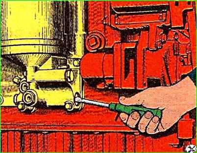
Final adjustment of the valve (Fig. 3) must be carried out on a running diesel engine to establish the oil pressure in the line within 0.25 ÷ 0.35 MPa at the nominal crankshaft speed and an oil temperature of 70 ÷ 80 ° C.
The pressure reducing valve must open at an oil pressure of 0.05-0.06 MPa in front of it and with oil bypass to the atmosphere.
The braked rotor on the axle must be checked for leaks at an oil pressure of at least 0.8 MPa in front of it and a back pressure at the filter outlet of at least 0.2 MPa.
In this case, the working fluid is allowed to leak through the rotor bearings from under the rotor nut (including along the thread) at a rate of no more than 0.067 dm3/s; oil leakage from under the rotor cup is not allowed.
On the KI-5278 test bench, with an oil flow rate through the rotor of 0.53 dm3/s and a pressure at the filter inlet of 0.7±0.02 MPa, the parameters must be as follows: pressure behind the filter - not less than 0.25 MPa; oil flow rate into the line - not less than 0.53 3/s; rotor speed not less than 5500 min -1.
The assembled filter must be tested for leaks for 1 min at a pressure at the filter inlet of 0.7÷0.8 MPa and a back pressure at the outlet of at least 0.2 MPa.
In this case, leakage or the appearance of oil drops on the outer surface of the filter and at the joints is not allowed.