Before checking the installation of the front wheels, check and, if necessary, adjust the axial clearances in the hub bearings and bring the tire pressure to normal
Wheel camber, lateral and longitudinal inclination of the kingpins and wheel turning angles are checked on special diagnostic stands or with the device mod. 2183, shown in Figure 1.
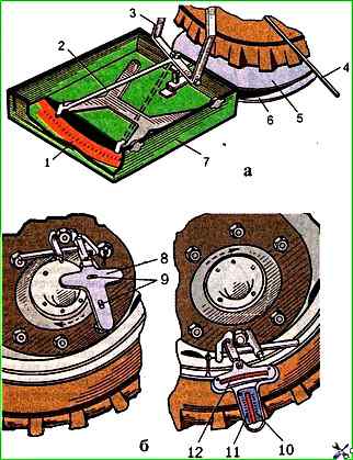
The device consists of an aluminum body, in which two installation levels (without scales) and two levels for measurement (with scales) are mounted.
The head is used to attach the device to the bracket, which is installed on the wheels of the car.
All scales are graduated in degrees: on the camber and longitudinal inclination scales of the kingpin, positive angles are indicated by a plus sign, and negative angles by a minus sign.
Two boxes 7 with scales 1 on the bottom and indicators 3 with extensions 4 are used to change the angles of rotation of the wheels.
The boxes are used to store and transport the device.
The kit includes two flat 5 and two spherical 6 disks to facilitate the rotation of the wheels of the vehicle being checked.
Checking and adjusting the toe-in of the front wheels
To adjust the front wheel alignment, do the following:
Place the car on a horizontal platform and set the front wheels to the position for driving straight ahead;
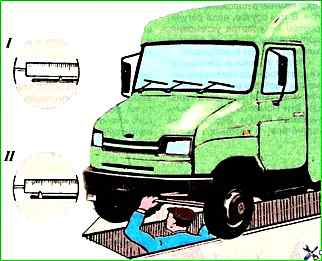
Insert a sliding ruler between the wheel rims in front of the front axle parallel to the platform at a height corresponding to the center of the wheel (Fig. 2).
Take a measurement and mark the location of the ruler;
Roll the car forward half a turn, the wheels and, having installed the ruler on the marks behind the front axle, take a measurement.
If adjustment is necessary, it is necessary to loosen the fastening of the tie rod clamps and, by rotating the tie rod pipe in one direction or another, achieve the required amount of wheel alignment.
After this, it is necessary to tighten the bolts of the tie rod clamps.
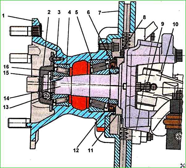
At the same time as checking and adjusting the wheel alignment, it is recommended to check and, if necessary, adjust the wheel turning angles using stops 9 (Fig. 3).
Checking the wheel alignment
To check the wheel alignment, the car is placed on a flat horizontal surface so that the front wheels are in a position corresponding to straight-line movement.
In this case, the wheel hub bearings must be adjusted, the tire pressure must be brought to normal.
The body of the device 8 (Fig. 1b) is secured with a clamp on one of the wheel fastening nuts with the back side up.
Using the bubbles of two mutually perpendicular installation levels, the body is installed horizontally.
After this, the wheel is rolled 180° so that the bubble of the level of the transverse tilt scale stopped against zero, and the camber angle is determined from the scale.
The camber angle of the wheels is not adjusted.
It changes only due to wear and deformation of the front axle parts and can only be restored during its repair.
Checking and adjusting the maximum steering angles
To measure the maximum steering angles, the front wheels are installed on the swivel disks 5 and 6 (Fig. 1a), connect the extensions 4 with the rods of the brackets of the indicators 3 of the rotary boxes.
Boxes 7 are installed at each wheel so that the extensions of the indicators fit tightly against the tires below the hubs, and the arrows 2 of the indicators are opposite the zero divisions of the scales.
The wheels must be set for straight-line movement and braked.
After this, the wheels are turned to the right and left to the stop and the turning angles are determined.
If necessary, adjust the angles using stops 9 (Fig. 3), which rest their heads against the lugs of the front axle beam.
To adjust, loosen the lock nut and set the the required angle of rotation.
The same should be done for the other wheel of the car.
After completing the adjustment, tighten the lock nut and remove the circles from under the wheels.
Checking the transverse and longitudinal inclination angles of the kingpin
These angles are determined simultaneously with measuring the maximum angles of rotation of the wheels.
First, the wheel is turned to the right by 20° according to the scale pointer of the left wheel, then the wheels are turned to the left by 20° from the zero division of the scale, each time setting the bubbles of the levels of the device 8 (Fig. 1a) to zero divisions, and the inclination angles of the kingpin of this wheel are determined according to the corresponding scales.
After checking the installation of the angles of one wheel, the device is installed on the other wheel and the same operations are performed.
The transverse and longitudinal inclination angles of the kingpin are not adjusted, but restored when repairing the front axle.