When removing the clutch from the vehicle, it is necessary to disconnect the clutch release drive. This work can be performed both with and without disconnecting the pipelines
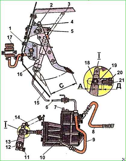
In the first case, put a hose on the bypass valve 7 of the PGU (Fig. 1), lower the free end of which into a vessel, unscrew the bypass valve by 0.5-1 turn and drain the liquid by pressing the clutch pedal several times.
Then disconnect the air 8 and hydraulic 9 hoses from the PGU, remove the release spring 1, unpin and remove the pin 18
Unscrew the bolts securing the PGU to the bracket on the gearbox and remove it.
In the second case, the hoses are not disconnected and the fluid is not drained from the PGU.
First, remove spring 14, then unpin and remove pin 18 (Fig. 1)
Unscrew the bolts securing the PGU to the gearbox bracket and secure the PGU with pre-prepared soft wire or rope to the vehicle chassis so as not to damage the pipelines.
Unscrew the nuts and remove the propeller shaft, disconnect the speedometer shaft.
Unscrew the bolts and remove the hatch in the cabin above the gearbox, and then the gear shift lever.
Unscrew the nuts securing the gearbox to the clutch housing and use a hoist or jack trolley to remove it.
Unscrew the bolts securing the bottom cover clutch housing and remove the cover.
Unscrew the clamping bolt securing the lever to the fork shaft, remove the lever.
Unscrew the two bolts securing the fork flange and remove it; remove the clutch release fork, having first moved it to the left and tilted it downwards.
The clutch assembly with the crankshaft is dynamically balanced at the factory, so it is necessary to mark the relative positions of the clutch and flywheel.
Unscrew the bolts securing the pressure plate housing to the flywheel. The bolts should be loosened gradually, turning the flywheel to avoid deformation of the casing.
Remove the pressure plate assembly with the casing, remove the driven disk.
Disassembling the pressure plate and clutch casing
Disassembling the clutch pressure plate and casing is usually done in order to replace the pressure plate levers due to wear of their spherical heads, replace damaged lever forks, and also to grind the pressure plate.
In other cases, disassembling the clutch is impractical; it is better to replace the entire unit.
Before disassembling, it is necessary to mark the relative positions of all clutch parts.
To disassemble the pressure plate, you need to use an auxiliary flywheel and a 9.8 mm thick steel disk that replaces the driven disk.
Instead of a steel disk, you can also use any hard gasket of the specified thickness.
If necessary, various devices with quick-release clamps can be used to disassemble the pressure plate, but with the obligatory installation of the pressure plate casing on eight centering studs or bolts, followed by pressing the casing by its paws to the flywheel.
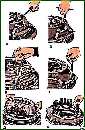
Using a screwdriver or chisel, bend back the petals of the locking plates, unscrew the plate fastening bolts and remove the locking and support plates from the casing (Fig. 2a).
Unscrew the bolts securing the paired tangential spring plates (Fig. 2c) and remove the guide bushings from the shaped holes in the plates, riveted to the casing at the other end.
First unscrew the adjusting nuts (Fig. 2b), then all the bolts securing the clutch casing to the flywheel (Fig. 2g).
Remove the clutch casing (Fig. 2d), pressure springs (Fig. 2e), and heat-insulating washers.
Mark the position of each clutch release lever relative to the pressure plate
Unpin and remove the pins (Fig. 2a) connecting the levers to the pressure plate, remove the levers assembled with the support forks and remove the needle rollers from the holes levers.
Unpin and remove the pins connecting the levers to the support forks, remove the forks from the levers and remove the rollers from the lever holes (Fig. 2b).
Remove the pressure plate from the flywheel.
")

")
")
")
")
")
")
")