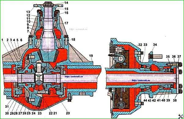
Adjusting the preload of the pinion bearings on the ZIL-5301 vehicle
The tapered roller bearings of the pinion must be adjusted with a preload by selecting adjusting washers 9, of which two pieces are installed.
The plant produces a set of washers with a thickness of 2.65-3.15 mm with a thickness difference of 0.1 mm.
The bearing tension should not exceed 0.1 mm.
Adjustment must be performed as follows:
Unscrew nut 14 without unlocking it.
This must be done carefully so as not to damage the thread.
It is recommended to lubricate the thread with oil.
First, turn the nut at a small angle so as to only cut off the extrusion on the nut and return the nut to its original position, and then unscrew it completely;
Unscrew the bolts securing the bearing cup to the axle housing and remove it from the housing along with the adjusting linings;
Install onto the press pads of the bearing cup and press out the drive gear together with the inner bearing ring 7, adjusting washers 9 and spacer sleeve 8.
If there is no press, the same operation can be performed with a hammer using a soft mandrel;
Remove the drive gear flange from the bearing cup;
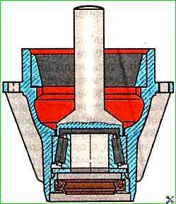
Turn the bearing cup over and using a mandrel installed on the inner race of the front bearing, press out its sleeve with the cuff assembly (Fig. 2);
Inspect the removed parts, replace faulty ones if necessary;
The thickness of the newly installed adjusting washers should be less by the gap value (provided that the other parts have not been changed), and the gap value is rounded up to tenths of a mm;
To check the correct selection of washers, assemble the cup in the reverse order, without installing the sleeve sleeve and installing the process flange without a mud deflector.
Tighten the flange nut (torque 400÷550 Nm), clamping the drive gear in a vice with soft metal gaskets, while turning the bearing cup so that the rollers take the correct position.
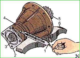
The correctness of the bearing preload is checked by the torque value (Fig. 3) required to turn the drive gear without the seal and mud deflector.
This value is 2.5÷4 Nm.
The torque must be measured during continuous rotation in one direction after at least five full revolutions of the shaft.
The bearings must be lubricated with the oil used for the main gear.
If the parts have been changed, then two washers can be selected empirically so that after the trial assembly there is a small gap, measure it with an indicator, and then select the washers as described above.
After the final adjustment of the bearings, press the seal housing together with the seal into the cup, having previously placed it between the working edges seals with consistent grease.
If the seal was removed from the housing, it is recommended to lubricate its mounting surface with engine oil before installing it in the housing.
Tighten the drive gear flange mounting nut and lock it by pressing its edge into the groove on the gear shaft.
When tightening the nut, do not forget to turn the drive gear or bearing cup so that the roller and the bearings are in the correct position.
Steel adjusting linings 18 (see Fig. 1) must be lubricated with spindle oil or industrial I-30 before installing the bearing cup in the crankcase, and thin linings must be installed on both sides of the lining set.
The bolts for fastening the bearing cup of the drive gear must be finally tightened to a torque of 70-100 Nm, while the drive gear must rotate smoothly, without jamming.
")

")
")
")
")
")
")
")