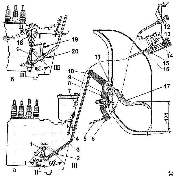
The fuel supply drive device is shown in Fig. 1.
The drive can be disassembled and assembled in any sequence.
When assembling the drive, it must be adjusted in the following order:

Adjust the length of rod 3 by rotating tip 2 with the lock nut loosened.
The length of the rod, measured between the centers of the connecting pin of the head and the hole in the tip, should be 378-382 mm;
Install the rod and assemble the drive as shown in Fig. 1.
Install the eye of the return spring 7 under the bolt securing the cover of the fine fuel filter;
Turn the handle 13 counterclockwise until it stops.
Move the lever 1 to the extreme left position "I" and, holding it in this position, install the clamp 4 at a distance of no more than 5 mm from the eye of the bracket;
Press the handle 12 of the diesel stop rod all the way;
Move the lever 1 to the extreme right position "III" and, holding it in this position, install clamp 5 at a distance of no more than 5 mm from the bracket of lever 6;
Check the ease of movement of handle 12.
When pulling the handle, spring 8 should easily compress, and lever 1 should move to the extreme left position "I";
Start the diesel engine and, focusing on the tachometer readings, adjust the crankshaft speed at idle with bolt 9 with the lock nut loosened.
Lock the bolt.
When the drive is correctly adjusted, the distance from the pedal pad to the cabin floor in a free state should be about 124 mm.
It should be borne in mind that the pedal does not have a hard stop when fully pressed, so do not apply excessive force to it at maximum crankshaft speed shaft.


