On the ZIL-5301, in addition to the voltage regulator relay, which is located to the left of the driver's seat below, there is also an excitation winding relay
The excitation winding relay is located on the relay panel on the right side, near the push-button fuse panel
This relay protects our excitation winding during starting with EFU, and when starting is difficult, especially in the cold season. Therefore, after starting, the following is observed:
- - no charge or weak charge;
- - tachometer readings at "0".
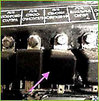
After a while, the relay turns on and charging appears.
Some comrades complain about the tachometer readings, such as - "the tachometer needle starts jumping".
This defect is caused by the burning of the contacts of this relay.
Let's consider below the main faults of the alternator current:
Excitation winding break
With this fault, an emf of up to 3-4 V is induced in the stator winding, caused by the residual magnetism of the rotor steel.
A contact failure in the brush assembly due to oxidation or oiling of the generator contact rings, severe wear or hanging of the brushes in the brush holders, a decrease in the elasticity of the brush holder springs, etc.
The fault is accompanied by an increase in the resistance of the generator excitation circuit, therefore the excitation current decreases, and along with this, the generator power drops.
The generator voltage reaches the rated value only at an increased rotor speed.
A turn-to-turn short circuit in the excitation winding coil is caused by the same reasons and leads to similar consequences.
A turn-to-turn short circuit is determined by measuring the winding resistance ohmmeter.
The excitation winding short-circuit to the housing most often occurs in places where the ends of the coils are connected to the contact rings.
The short-circuited coil is de-energized, the excitation magnetic flux decreases sharply, so the generator voltage will become lower and the current from it does not flow into the external circuit.
This malfunction is determined using a voltmeter or a test lamp with a voltage of 220-500 V, connecting one conductor to the rotor iron, and the other to the contact ring.
If there is no current in the circuit for 1 minute, then the winding insulation is good.
Open circuit of the stator phase winding
If there is an open circuit in the connecting wire of one phase of the generator to the rectifier terminal, the phase is turned off, and therefore the resistance of the stator winding increases significantly, which reduces the generator power.
When If two phases are broken, the entire stator winding circuit is interrupted, and the generator will not work.
With the generator disassembled, to determine the break in the stator phase winding, it is necessary to alternately connect two phases of the winding to the battery through a light bulb or voltmeter.
The presence of a break turns off the circuit, and there will be no current in it.
A short circuit of the stator winding to the housing occurs due to mechanical or thermal damage to the insulation of the winding and terminal clamps.
The malfunction significantly reduces the useful power of the generator as a result of a short circuit of the faulty phase windings through the rectifier and the housing.
These faults are determined by a test lamp with a voltage of 220-500 V, by connecting one conductor to the stator core, and the other to one of the stator winding terminals.
A defective insulation is replaced with a new one.
In addition to the above faults, mechanical faults also occur in DC and AC generators, such as wear and tear of bearings, wear of the anchor shaft (rotor) journals, development of the shaft and pulley keyway, damage to the threads on the shaft and in the nuts, etc.
Identifying and eliminating such faults does not present great difficulties.
Main faults of generator rectifiers
Short circuit to the housing of the "+" terminal
This fault causes a short circuit of the rectifier, and in the circuit - the stator winding of the generator - rectifier, a high current is established, as a result of which they overheat and the destruction of the winding insulation and breakdown of the blocking layer of the rectifier diodes are possible.
Breakdown of the diodes most often occurs due to an increase in the generator voltage, which can be breakage of the main winding of the voltage regulator, breakage of the wire connecting the relay-regulator to the housing, incorrect adjustment of the voltage regulator, disconnection of the wire from the "+" terminal of the generator.
In addition, breakdown of the diodes occurs when the rectifier is overheated by a high current that passes through them, as well as in case of mechanical damage to the diodes, when the rectifier terminals are incorrectly connected (when the negative terminal is connected not to the housing, but to relay-regulator clamp).
At the breakdown site, the metal covering layer melts, resulting in a short-circuited section between the diode electrodes.
In the event of a diode breakdown, there will be a large discharge current when the generator is not working.
Aging of diodes. Over time, the diodes disintegrate and age, which increases the resistance in the rectified current circuit.
This malfunction causes an increase in the voltage drop at the diode terminals when current passes in the forward direction and an increase in the reverse current.
As a result, the battery will be undercharged.
The generator is mounted on the engine and is driven by the engine crankshaft pulley.
The generator is attached to the engine with two paws through a bracket and with a third paw to the tension bar, when moving along which the generator drive belt is tensioned.
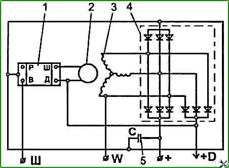
The schematic diagram of the generator is shown in the figure.
Attention!
Disconnect and connect the wires to the generator only with the battery disconnected.
Proper operation of the generator is ensured only if all contacts are securely electrically connected, including between the generator housing and the engine.
Operation of the generator with the battery disconnected can damage the voltage regulator, as well as other consumers of the on-board network.
Maintenance and repair of the generator should be carried out only in specialized workshops by qualified specialists.
Check the rectifier unit only on a disassembled generator with a disconnected stator winding.
Check only from a DC source with a voltage of no more than 24 V, connected in series with a test lamp.
Maintenance generator
To ensure generator operation, it is recommended to keep the generator clean and follow the following maintenance rules.
Check the generator's performance daily using the readings of the control lamp and voltmeter located in the instrument cluster on the dashboard.
When the engine is started, the control lamp should light up and go out after the engine is started.
During normal generator operation, the voltmeter needle is in the green zone of the "G" scale (generator).
If the voltmeter needle is in any of the red zones of this scale, the generator is faulty.
The condition and tension of the drive belts should be checked daily.
During TO-1, check using measuring instruments.
Particular attention should be paid to the tension of the belts at the beginning of their operation (1-2 days).
The belt tension is adjusted so that when you press the the middle of the belt with a force of 4 kgf, the deflection was within 10-15 mm.
When installing new belts, it is permissible to set a smaller deflection value - 10 mm.
The belt tension is adjusted using a tension bar. To do this, after loosening the generator mount to the bracket and bar, move the generator body to the required position and secure it.
Attention! If the belt tension is weak, the generator will not deliver full power.
If the belt tension is excessive or skewed, the generator will fail prematurely.
The criterion for the limit state of the belt is delamination of more than 1/3 of the length, the presence of rubber cracks down to the cord and the impossibility of compensating for elongation in the drive.
When checking the tension and installing a new belt, check for damage, oiliness of the pulley groove surfaces and the location of the pulley grooves in the same plane.
At least once a month, it is recommended to check the degree of contamination of the batteries, which should be at least 75%.
During TO-2 without removing the generator from the engine, check the fastening of the generator to the engine and the fastening of the nuts of the tie bolts of the covers.
Check the tightening and cleanliness of all places where the wires are connected to the generator and batteries batteries.
If necessary, clean the connection points, tighten the contact nuts and screws.
During each seasonal maintenance (without removing the generator), check the condition of the brush assembly in the following order:
- Disconnect the wire from the "Ш" terminal of the generator.
- Unscrew the screws securing the brush holder and carefully remove it.
- Check free movement (without jamming or jerking) of the brushes in the brush holder guides.
- Check the height of the brushes, which should be at least 8 mm. Replace the brushes if necessary.
")

")
")
")
")
")
")
")