Front wheel brake mechanisms of ZIL-5301
The design of the front wheel service brakes is shown in Fig. 1.
To remove the brake discs from the wheel hubs, unscrew bolts 1.
Before disassembling the floating brake caliper (Fig. 2), it must be thoroughly cleaned of dirt and washed, and the clamp 21 for fastening the hoses must be removed from it.
Then put a rubber hose on the bleed valve 10 and lower its end into a clean container.
Unscrew the bleed valve one turn and, pressing on the body 11 of the caliper, push the pistons of the cylinders into the body.
A certain amount of brake fluid will flow into the container.
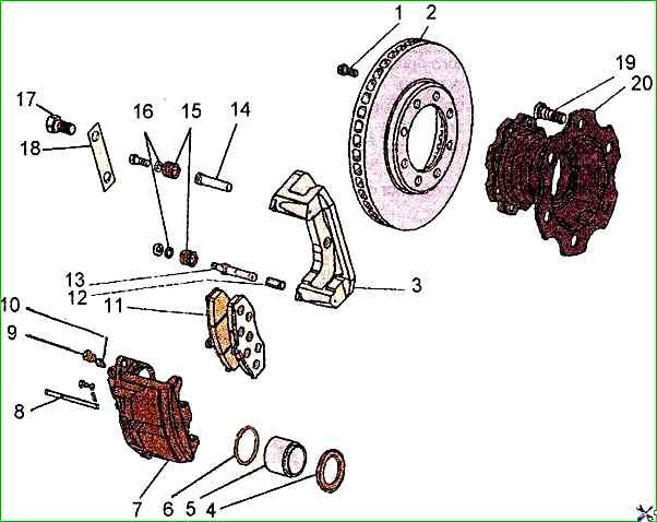
To remove the brake pads, remove pin 8 from retaining pin 7 and pull out the pin.
Then, holding upper guide pin 13 from turning with a special key, unscrew bolt 15 of its fastening to the axle housing, protecting rubber boot 14 of the pin from damage.
Lift (turn) caliper housing 11 relative to second pin 17 until it stops against the caliper and remove brake pads 6.
Unscrew nut 18 of auxiliary pin 17 and remove caliper housing 11.
Remove piston dust covers 5 and carefully, so as not to damage the surface, push pistons 3 out of the cylinders, using compressed air.
Remove the sealing rings 4 from the grooves without damaging the inner surface of the cylinders.
Clean and wash the brake mechanism parts with ethyl hydrolysis alcohol according to GOST 18300-72. The pistons should be washed especially thoroughly with alcohol.
Using other liquids for washing is prohibited.
Without wiping the parts, let them dry in the air, laying them on clean glossy paper that does not leave lint.
Check the condition of all parts of the service brake.
If the working surface of the piston is damaged or has traces of corrosion, the piston should be replaced.
If the surface of the cylinder is damaged, the caliper housing should be replaced.
The surface of the brake discs should be smooth.
Scratches and small burrs that appear after normal operation of the brakes are not a defective feature, but a disc with severe burrs should be replaced.
If it is impossible to replace the disc, it is allowed to grind it together with the hub.
Grinding should be performed by qualified personnel on special equipment.
The ground surfaces of the disc must have a deviation from flatness of no more than 0.04 mm and from parallelism of no more than 0.04 mm and have a roughness of 0.8 µm.
The runout of the disc relative to the mounting surfaces of the hub must not exceed 0.1 mm.
There must be no sharp edge on the inner circumference of the ground surface.
Both sides of the disc must be ground to the same value, but the overall thinning of the disc must not exceed 3 mm.
Before assembling the brake caliper, do the following.
Lubricate the working surfaces of the cylinders and pistons with unused brake fluid.
Install new sealing rings 6 (see Fig. 1) into the grooves of the cylinders of the bracket housing 7.
Lubricate the surface of the cylinders up to the groove with a thin layer of DT-1 grease.
Carefully, so as not to damage the polished surface, insert the pistons 5 into the cylinders with the open end facing outward.
Put the edges of the new protective covers 15 on the pistons 5.
Lubricate the pistons in the area of the covers with DT-1 grease.
Put the free edges of the protective covers on the cylinders.
By inspection, it is necessary to determine the condition of the pins 13 and 14, on the surface of which there must be no scratches, noticeable signs of wear and damage to the threads, damaged pins must be replaced.
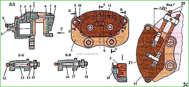
Remove the bushing 16 of the auxiliary pin (see Fig. 2).
Clean the pins and the holes for them in the calipers, and wash them with alcohol.
Install the body of the caliper 11 on the caliper 1.
Put a new bushing 16 on the auxiliary pin 17.
Lubricate the working surfaces of the pins with TSIA-TIM-221 grease and insert the pins into the holes of the caliper 1.
Install new protective pin covers 14 and tighten the guide pin fastening bolt 13 and the nut 18 of the auxiliary pin, protecting the protective covers from damage.
Install the clamp 21 of the brake hoses on the caliper 20.
After this, you need to install the brake caliper on the front axle steering knuckle and secure it.
Secure the brake hoses in the bracket, as shown in Fig. 2, preventing them from twisting, and connect to the pipelines.
Install the brake pads 6 and secure them with pin 7.
Install the pin 8.
From operating experience: It is practically useless to repair the front calipers at home. It will be cheaper to immediately buy a new caliper and install it on the car.