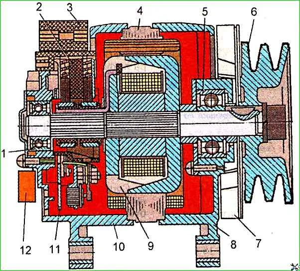
ZIL-5301 vehicles and its modifications are equipped with an alternating current generator mod. 2022.3701, ZIL buses are equipped with an alternating current generator mod. 3882.3701
Both generators with built-in rectifiers and a K73-21V capacitor.
The generator is installed on the right side of the engine (in the direction of travel) and is driven by two belts (L = 1320, S = 8.5x8).
Technical characteristics of the generator
Nominal voltage 14 V
Maximum current - 110 A
Rotor speed at which the generator voltage reaches 12.5 V, min -1, no more than:
- - at a current of 0 - 1000 min -1
- - at a current of 30 A - 1400 min -1
- - at a current of 60 A - 2000 min -1
- - at a current of 100 A - 3500 min -1
Removing and installing the generator on the car
To remove the generator from the car, you must:
Loosen the bolts securing the generator to the bracket;
Unscrew the bolt securing the generator to the tension bar and remove the belts;
Unscrew the bolts securing the generator to the bracket and remove the generator.

The generator must be installed in the following sequence:
Loosen the bolt of the terminal connection on the bracket, install the generator mounting bolts to the bracket and tension bar and install the belts;
Using a mounting blade or other lever, move the generator, tension the belts and tighten the generator mounting bolt to the tension bar; tighten the generator mounting bolts to the bracket.
CAUTION!
To avoid damage to the generator covers, tighten the terminal connection bolt last.
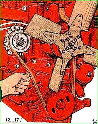
The tension of the drive belts is adjusted so that when pressing on the middle of the largest branch of each belt with a force of 40 N, their deflection is within 12-17 mm or when pressing with the same force on the middle of the horizontal branch of each belt, their deflection is within 6-9 mm.
When assembling, keep in mind that the grooves of the generator pulley and the engine pulley must be in the same plane.
Skewing of the drive belt is not allowed.
Checking the correct installation and tension of the belts can also be done using the device mod. KI 8920
Connection of wires to the terminals of the generator, voltage regulator and batteries must be carried out strictly in accordance with the markings indicated on the terminals of the generator and regulator.
Incorrect connection of wires can lead to failure of the generator, voltage regulator and batteries.
Warning:
To disconnect the wire from the brush holder, pull only the connector block, not the wires.
Disconnect and connect wires to the generator only with the battery disconnected.
Proper operation of the generator can only be ensured if there is good contact in the circuit between the generator body and the regulator.
The connector block in the brush holder must be fixed until click.
Caution!
It is prohibited to short-circuit the generator terminals even for a short time
Disassembling the generator
It is recommended to disassemble the generator in the following order.

- 1. Secure the generator in a vice.
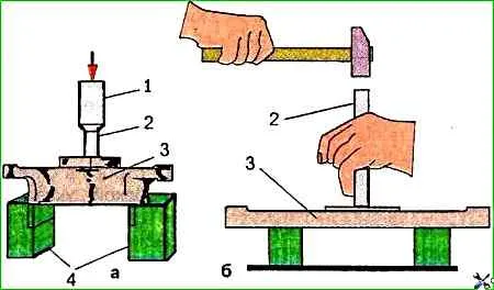
- 2. Remove the brush holder by unscrewing the two mounting screws.
- 3. Unscrew the two screws securing the phase block to the cover, disconnecting the wires and removing them.
- 4. Remove the ball bearing cover.
- 5. Unscrew the tie rods.
- 6. Remove the generator cover from the slip ring side together with the stator, using the puller mod. И 804.31.000.
- 7. Disconnect the stator phase windings from the rectifier unit terminals, remove the stator.
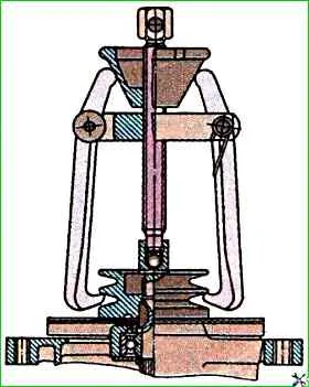
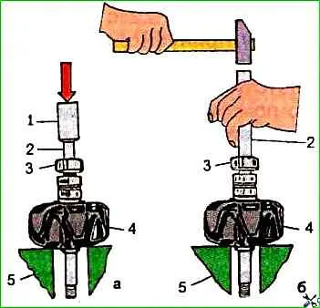
- 8. Unscrew the pulley mounting nut and remove the pulley using the puller mod. И 804.31.000.
- 9. Remove the fan, spacer sleeve and take out the key
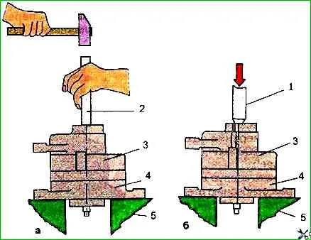
- 10. Remove the cover from the drive side using the puller mod. And 804.32.000, or on the press.
- 11. Unscrew the four screws and press the ball bearing out of the cover seat on the drive side
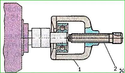
- 12. Remove bearing 6 from rotor shaft with puller or press
Generators are assembled in reverse order.
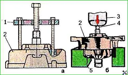
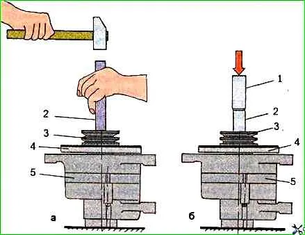
- Installing the rear bearing on the rotor shaft
- Pressing on the cover from the contact ring side
- Installing the generator pulley
Before installing the bearings, they must be greased with TSIA-TIM-221.
")

")
")
")
")
")
")
")