Adjusting the fuel supply ZIL-5301
To adjust the amount and uniformity of fuel supply by the pump sections, do the following.
Before adjusting the pump for uniformity and amount of fuel supply by each section, check:
- tightness of the delivery valves by shutting off the fuel supply with the control lever.
Fuel leaks are not allowed. In case of leakage, replace the delivery valve assembly;
- - fuel pressure in the suction cavity of the fuel pump, which should be 0.07-0.13 MPa;
- - absence of air leaks at the joints of the fuel lines.
Adjust the amount of fuel supply by each section of the pump and. uniformity of feed by sections at a rotation speed of 1200 min-1 in accordance with the adjustment table.
Fuel feed unevenness control shall be carried out in accordance with GOST 10578.
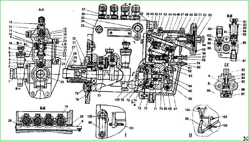
Adjust the cyclic fuel supply at the nominal rotation speed using the hard stop 60 (see Fig. 1).
When the bolt is screwed in (inside the housing), the supply increases, when it is unscrewed, it decreases.
Adjust the fuel supply in the maximum torque mode (700-800 min -1) by changing the position of the corrector screw 71.
To achieve the rotation speed corresponding to the corrector being switched off (complete recession of the corrector rod), it is necessary:
- at an overestimated speed (more than 800 min) - unscrew the adjusting screw from the corrector housing;
- at a underestimated rotation speed (less than 700 min -1) - screw in the screw into the corrector body.
The value of the cyclic feed is determined by the stroke of the corrector rod, which should be equal to 0.5-0.7 mm.
To determine the parameters for correcting the cyclic feed, it is necessary to determine the cyclic feeds in the rotation speed range expanded in comparison with the adjustment table by 50 min -1 in each direction after 50 min -1.
To calculate the maximum correction coefficient, the largest (of those measured) cyclic gear should be selected.
The uniformity of fuel supply and the performance of each section of the pump should be adjusted by moving the rotary sleeve relative to the toothed ring with the tightening screw loosened.
When When turning the sleeve to the left, the fuel supply to the section increases, when turning to the right, it decreases.
After adjusting the pump section, tighten the toothed ring nut screw securely.
If it is necessary to change the fuel supply of all 4 sections at the same time, it is permissible to change the position of the hard stop, after which it is necessary to check the start of the regulator action and the uniformity of the fuel supply by sections.
Check the amount of fuel supply at the maximum idle speed, which should be 22.5 mm 3 cycle at a speed of 1250 min -1.
Screw bolt 56 (see Fig. 1) with the idle spring at the maximum idle speed until the free end of the spring touches the main lever of the regulator and lock it with a nut.
Check the cyclic fuel supply at a speed of rotation speed of 90-100 min -1, corresponding to the starting mode.
The average cyclic fuel supply at this rotation speed must be at least 140 mm/cycle when the control lever is set to the stop against the maximum rotation speed screw.
Check the forced complete shutdown of the fuel supply at a rotation speed of 100 min -1 by moving the regulator control lever to the extreme position towards decreasing the supply.
Adjusting the boost corrector
The start of the rod movement must occur at an air pressure in the above-diaphragm space equal to 0.005-0.010 MPa.
In the absence of pressure in the above-diaphragm space, the average cyclic supply is set by moving the stop 46 (see fig. 1) and should be 60-70 mm 3/cycle at a pump camshaft speed of 550 min -1.
The start of movement of diaphragm 51 (rod 54) should be adjusted by changing the preliminary compression of the spring by screwing in or out sleeve 50.
Movement of sleeve 50 towards the diaphragm increases the air pressure corresponding to the start of operation of the diaphragm; the movement of the sleeve from the diaphragm reduces the air pressure corresponding to the start of the diaphragm operation.
After adjusting the start of the diaphragm (rod) movement, install pin 49 in the hole in the corrector housing.
When installing the pin, ensure that its upper end does not protrude above the upper plane of the KPN housing, for which, if necessary, turn the corrector sleeve 50 in one direction or another by no more than 30°.
The pressure of the start of the diaphragm (rod) movement must remain within the established limits.
The pressure corresponding to the end of the KPN operation is determined by a series of successive measurements of the performance of the pump sections at the corresponding rotation frequency of the camshaft of the fuel pump.
The end of the KPN operation should be at a frequency of 550 min -1 and a pressure of 0.012-0.015 MPa.
")

")
")
")
")
")
")
")