Repair ZIL-5301
The ZIL-5301 "Bychok" is a light-duty truck whose specifications vary depending on the model, but generally speaking, it features a 4.75-liter diesel engine (producing between 109 and 130 hp), a payload capacity of approximately 3–3.5 tons, and a top speed of 95 km/h.
Key features include rear-wheel drive, a five-speed manual transmission, and reinforced suspension with leaf springs.
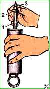
To assemble the shock absorber, you need to:
Install the compression valve body in a vice and secure the compression valve stem.
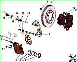
The design of the front wheel service brakes is shown in Figure 1
")

")
")
")
")
")
")
")