Repair ZIL-5301
The ZIL-5301 "Bychok" is a light-duty truck whose specifications vary depending on the model, but generally speaking, it features a 4.75-liter diesel engine (producing between 109 and 130 hp), a payload capacity of approximately 3–3.5 tons, and a top speed of 95 km/h.
Key features include rear-wheel drive, a five-speed manual transmission, and reinforced suspension with leaf springs.
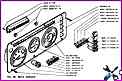
Instrument panel of the ZIL-5301 vehicle catalog
The instrument panel contains indicators, warning lamps and switches
The figure shows the installation locations of the parts and their designations according to the spare parts catalog.
We look at the figure and the table shows the decoding of the part.
")

")
")
")
")
")
")
")