Basic instructions for disassembling and assembling the D-245E3 water pump
Disassembling the water pump
Remove the pump from the engine.
Unscrew nut 9 (Figure 1) securing the water pump drive pulley.
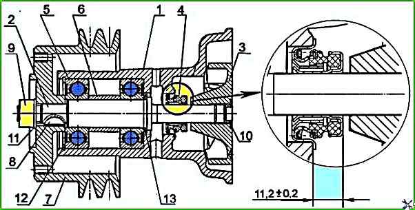
Using a puller, remove pulley 7 of the water pump.
Remove ring 12 from the pump housing, which locks the bearing unit.
Remove plug 10 from the end of impeller 3, remove the impeller from the pump shaft 2, using the threaded hole in the end of the impeller (M18x1.5), using a special bolt.
Press out the shaft with bearings from the water pump housing.
Press out in the direction of pulley installation.
Press the bearings off the shaft.
Remove thrust ring 13.
Press out the oil seal from the pump housing.
Parts defect.
Disassembling the water pump with an electromagnetic fan clutch
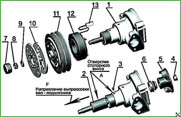
Disconnect plug connector 13 (Figure 2) and remove the pump from the diesel engine.
Remove cap 7, unscrew nut 8 (left-hand thread), remove washer 9 and fan housing 10.
Using a puller, remove pulley 11 and electromagnet with flange 12.
From the water pump housing, unscrew lock screw 3.
From the end of impeller 5, remove plug 4 and remove the impeller from the pump shaft, using the threaded hole in the end of the impeller (M18x1.5), using a special bolt.
Press out the bearing shaft from the water pump housing pump.
The pressing direction is shown in the figure.
Press out the seal 6 from the water pump housing.
Dismantling the water pump with a viscous fan clutch
Unscrew the bolts 3 (Figure 3) securing the spacer 2 with the fan 1 to the pulley 7 (Figure 3) of the water pump.
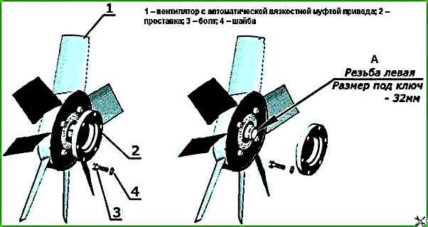
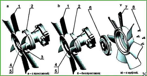
Note: if it is necessary to replace the viscous coupling of the fan drive, hold the spacer 2 and unscrew the coupling with the fan using the S =32 key (left-hand thread), then unscrew the four bolts 8 (Figure 5) securing the coupling to the fan.
Unscrew the nut 9 (Figure 1) securing the pulley 7.
Using a puller, remove the pulley 7 of the water pump, remove the key 8.
Remove the ring 12 from the pump housing, which locks the bearing assembly.
Remove the plug 10 from the end of the impeller 3, remove the impeller from the shaft of the pump 2, using the threaded hole in the end of the impeller (M18x1.5), using a special bolt.
Press out the shaft with bearings from the water pump housing. Press out in the direction of pulley installation.
Press out the bearings from the shaft.
Remove thrust ring 13.
Press out the seal from the pump housing.
Inspect the parts for defects.
Assembling the water pump
Install thrust ring 13 on the pump shaft, press in the bearings.
Fill the bearings and bearing cavity with 45 grams of Litol 24-ML and 4/12-3 grease
Press the shaft with bearings into the pump housing.
Install ring 12, which locks the bearing assembly.
Install the pump pulley, washer and nut. Tighten the nut to a torque of 120-140 Nm.
Using a mandrel, press the water pump seal 4 onto the inner housing whisker on the water pump shaft and, at the same time, press the outer housing of the seal into the water pump housing until the flange of the seal housing stops against the mating surface of the pump housing.
In this case, the design of the mandrel must ensure that the inner housing of the seal is pressed in such a way that the end surface of the inner housing is located at a distance of 11.2±0.2 mm from the mating surface of the pump housing.
Press the impeller onto the shaft, install the plug in the end of the impeller.
The recession of the end of the impeller relative to the mating plane of the pump housing must not exceed 0.3 mm, the protrusion of the impeller is not allowed.
Install the water pump on the diesel engine.
Fasten the spacer with the fan on the pulley of the water pump or the fan.
Assembling the water pump with an electromagnetic fan clutch
Press the bearing shaft into the pump housing so that the holes for the locking screw in the bearing housing and the water pump housing are aligned.
Tighten the locking screw.
Using the mandrel (Figure 4), press the water pump seal with the inner housing onto the water pump shaft and, at the same time, press in the outer seal housing into the water pump housing until the seal housing flange abuts the mating surface of the pump housing.
The design of the mandrel must ensure that the inner seal housing is pressed on in such a way that the end surface of the inner housing is located at a distance of 11.2±0.2 mm from the mating surface of the pump housing (the installation dimension is shown in Figure 1).
Press the impeller onto the shaft.
The recession of the impeller end relative to the mating surface of the pump housing must not exceed 0.3 mm, the impeller must not protrude.
Install a plug into the end of the impeller.
Press the electromagnet with the flange onto the pump housing (the outer diameter of the mandrel during pressing must not exceed the diameter of the flange hub).
Press the pulley onto the shaft.
Install the fan housing and washer on the shaft.
Tighten the nut (left-hand thread), ensuring a torque value of 120-140 Nm and install the cap.
Install the water pump on the diesel engine and connect the plug connector.
")

")
")
")
")
")
")
")