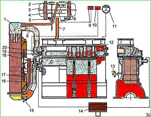
The diagram of the diesel liquid cooling system with forced circulation of coolant from a centrifugal pump is shown in Figure 1
The temperature of the coolant in the system is monitored by the temperature gauge, the sensor of which is installed in the rear part of the cylinder head.
In addition, a coolant emergency overheating sensor is installed in the liquid pump housing
On cars and buses of the latest series of production, instead of the liquid level control valve, a coolant level indicator sensor 5 is installed in the expansion tank.
Do not operate the diesel engine when the coolant overheating alarm lights up.
The coolant temperature in the cooling system must be maintained within 75°- 95°C.
When opening the expansion tank cap when the engine overheats, remember that steam may escape from the tank neck, causing burns to the face and hands.
A thermostat with a solid filler is used to speed up the warming up of the diesel engine after starting and to automatically regulate the temperature regime under various loads and ambient temperatures.
The liquid pump, fan and generator are driven from the diesel crankshaft pulley using two V-belts.
Litol-24 grease in the bearing the pump body cavity is laid during the pump assembly at the factory and does not require replenishment during the entire period of diesel operation.
The lubricant is replaced only after disassembling the liquid pump.
Checking the tightness of the diesel cooling system and the condition of the radiator cap valves using the DSO-2 indicator
A float is placed in the device body, with the help of which the moment of operation of the expansion tank cap valves adjusted to a certain pressure is recorded.
When taps 3, 13 are closed, pressure is created in the air cylinder.
Using a reducer, it is set to 0.15-0.16 MPa.
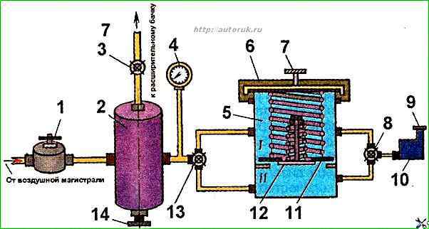
The plug removed from the neck of the expansion tank is fixed on the glass 5.
When tap 8 is closed, air is supplied to the upper cavity of the glass.
The lower cavity of the glass is connected to the indicator using tap 8. The pressure acting on the steam valve is recorded by a pressure gauge at the moment the float rises in the indicator.
Then connect the indicator to the lower cavity of the glass, and air is supplied from the air cylinder to the upper cavity and the pressure at which the air valve of the plug opens is recorded.
To check the tightness of the cooling system with the DSO-2 device, it is necessary to install the nozzle of the device on the neck of the expansion tank instead of the plug, connected to tap 3.
With taps 3 and 13 closed, the reducer creates a pressure of 0.6-0.7 MPa and open valve 3.
Use a stopwatch and pressure gauge to monitor the pressure change in the cooling system.
At the same time as checking the tightness of the system, you can also check the condition of the cylinder head gasket on a running diesel engine.
For this check, set the minimum crankshaft speed and monitor the pressure gauge readings.
Fluctuation of the pressure gauge needle indicates the flow of gases from the cylinders into the cooling system, i.e. damage to the gasket or the cylinder head itself.