Repair ZIL-5301
The ZIL-5301 "Bychok" is a light-duty truck whose specifications vary depending on the model, but generally speaking, it features a 4.75-liter diesel engine (producing between 109 and 130 hp), a payload capacity of approximately 3–3.5 tons, and a top speed of 95 km/h.
Key features include rear-wheel drive, a five-speed manual transmission, and reinforced suspension with leaf springs.
The diesel air supply system includes an air filter and pipes connecting the filter to the turbocharger
- Assembly of the rear axle ZIL-5301
- Cylinder block, crank mechanism (requirements)
- Pneumatic chamber ZIL-5301
- Design of spring energy accumulator ZIL-5301
- Brake malfunctions ZIL-5301
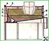
- Liquid heater for diesel engine ZIL-5301
- Running-in and testing of the D-245 diesel engine
- Seals (cuffs) ZIL-5301
- Brake force regulator ZIL-5301
- Front hub design ZIL-5301
")

")
")
")
")
")
")
")