Repair ZIL-5301
The ZIL-5301 "Bychok" is a light-duty truck whose specifications vary depending on the model, but generally speaking, it features a 4.75-liter diesel engine (producing between 109 and 130 hp), a payload capacity of approximately 3–3.5 tons, and a top speed of 95 km/h.
Key features include rear-wheel drive, a five-speed manual transmission, and reinforced suspension with leaf springs.
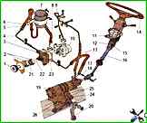
Installing the steering gear of the ZIL-5301 vehicle
Install the steering gear with hydraulic booster on the frame using the KZ-0352 device and secure it with bolts
- The design of the triple safety valve ZIL-5301
- Setting the ignition timing of diesel D-245E3
- Diagnostics of brakes ZIL-5301
- Pneumohydraulic amplifier of the car ZIL-5301
- Removal and disassembly of the clutch ZIL-5301
- Injector D-245
- Hydraulic drive pressure regulator ZIL-5301
- Assembly of the front axle ZIL-5301
- ZIL-5301 door drive diagram
- Checking the tension of drive belts D-245E3
")

")
")
")
")
")
")
")