Kamaz car
KAMAZ vehicles are designed for operation at ambient temperatures of plus 40... minus 40 °C, relative air humidity up to 80% at 20 °C, dustiness up to 1.0 g/m³, wind speed up to 20 m/s, and in areas located at an altitude of no more than 3000 m above sea level.
KAMAZ-5320 is a truck-trailer with a flatbed truck with a carrying capacity of 8000 kg, designed to work with a trailer with a gross weight of 11,500 kg; basic trailer mod. 8350 with a carrying capacity of 8000 kg;
KAMAZ-5410 (Fig. 2) is a truck tractor with a fifth-wheel load of 81 kN (8.1 tf), designed to work with a semitrailer with a gross weight of 19,100 kg; basic semitrailer mod. 9370 with a carrying capacity of 14,200 kg;
KAMAZ-55102 dump truck tractor with a 7,000 kg carrying capacity, equipped with a side-dumping platform, and designed to tow a trailer with a gross vehicle weight of 11,500 kg; base dump trailer mod. 8527 with a 7,000 kg carrying capacity, side-dumping.
KAMAZ-55111 is designed for transporting various bulk construction and industrial cargo with a total weight of up to 13,000 kg on roads designed for vehicles with an axle load of 100 kN (10 tf);
KAMAZ-53212 truck tractor with a flatbed platform with a 10,000 kg carrying capacity, designed to tow a trailer with a gross vehicle weight of 14,000 kg; base trailer mod. 8352 with a 10,000 kg load capacity;
KAMAZ-53211 and KAMAZ-53213 chassis designed to accommodate specialized bodies and various equipment and operate on roads rated for vehicles with an axle load of 100 kN (10 tf);
KAMAZ-54112 tractor unit with a fifth wheel load of 111 kN (11.1 tf), designed to tow a semitrailer with a gross vehicle weight of 26,000 kg; base semitrailer model 9385 with a load capacity of 20,500 kg.
Purpose, design and operation of the EFU
The device is designed to facilitate starting a cold engine at air temperatures down to -25 °C, quickly return the engine to normal temperature conditions and reduce smoke that occurs in a cold engine.
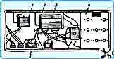
- KamAZ car power supply scheme
- Scheme of instrumentation of the KamAZ car
- Scheme of the light signaling system of the KamAZ car
- Scheme of outdoor and indoor lighting KAMAZ
- Troubleshooting in the KamAZ power supply system
- Troubleshooting in the KAMAZ electric start system
- Troubleshooting in lighting and signaling systems KAMAZ
- Heating and ventilation system of KamAZ car
- Windshield wiper system of KamAZ car
- The main failures of the starting heater of the KamAZ car
")

")
")
")
")
")
")
")