Analysis of circuit diagrams of lighting systems, light and sound alarms allows us to draw the following conclusions: - the circuits have general and private branches;
- - when the system is turned on, as a rule, several receivers are turned on;
- - the current of the receivers is controlled by an ammeter.
Based on these features, we choose the following troubleshooting method:
- - if one of the receivers fails, we establish which receivers of this branch work and which do not;
- - by analyzing the circuit diagram and current paths to serviceable and faulty receivers, we localize the faulty branch (or part of it);
- - using the midpoint method and knowing the duration of the checks, we find the faulty element.
The most typical and common malfunctions of the external lighting system (see Fig. 1) include:
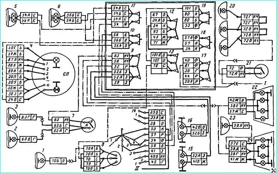
- one of the lamps does not light. Let’s say the high beam of the right headlight does not light.
According to the accepted methodology, we establish which receivers do not light up.
After making sure that all other lamps are on, we proceed to the second step, i.e. we localize the faulty circuit.
The common branch for the main beam headlights is the area from the power source to fuse 11.
Since the left headlight is on, it means that the general circuit is working, only the section from the fuse to headlight 6 (the wire and the lamp filament) is faulty. We do the same if there is a malfunction of the left headlight, side lights, etc.;
- several lamps do not light up, for example, the high beam of both headlights does not light up.
We proceed similarly to the previous example.
We check the serviceability of all other receivers of the external lighting system and make sure that they are lit.
We localize the area according to the diagram. The common area will be from the power supply to combination switch 14 (pin 54).
Since all other circuits are working, the section to be analyzed is: pin 54 - switch 14 - fuse 11.
Since we assume that there is only one fault in the circuit, the circuits from the fuse are OK.
Less time is required when checking the fuse. To do this, just press its button. If the light appears, the fuse is faulty; if not, the wire or terminals are faulty.
")

")
")
")
")
")
")
")