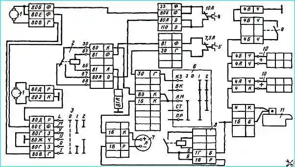
The heating and ventilation system is designed to maintain optimal temperature conditions in the cabin when the ambient temperature changes
Two electric motors pump air into the cabin through the heater radiator.
The radiator is included in the engine cooling system through a shut-off valve, which is turned on by a lever from the cab.
When the tap is turned on, the engine radiator pumps warm air into the cabin, and the system operates in heater mode.
When the radiator is turned off, the engines pump cold air into the cabin, and the system operates in ventilation mode.

The schematic electrical diagram of the heating and ventilation system (Fig. 1) includes two ME250 electric motors, an electric motor relay of type 11.3747.010, and a key switch of type A147-01.11, which controls the operating modes of the electric motors. The latter operate in two modes depending on the position of the key switch, which connects them in series or parallel.
The voltage to the electric motors is supplied by the electric motor relay through a 10 A fuse, and the voltage to the electric motor relay winding is supplied from the “K3” terminal of the instrument switch and starter through a 7.5 A fuse.
Therefore, electric motors can be turned on with a key switch only after turning on the instrument switch and starter to position “1”
The operating order of the system is as follows:
- - When the battery (ground) switch is turned on, the voltage from the batteries is supplied through an ammeter to the “AM” terminal of the instrument switch and starter and then to terminal 30 of the heater motor relay;
- - when the instrument switch and starter are installed in position II, voltage is supplied from terminal K3 through a fuse for a current of 7.5 A to the relay winding of the electric motors (pin 85), the relay is activated and supplies the voltage of pin 30 to pin 87 and then through fuse for a current of 10 A for terminals 80B and 80E of the electric motor (upper in the diagram) and terminal 80E of the heater motor switch;
- - when the electric motor switch is turned on to position “1”, its terminals 80V - 80G and 80D are closed, and the electric motors are connected in series relative to the on-board network voltage and operate at low speed, since each engine will have half the on-board network voltage.
Current path for powering electric motors:
“+“ battery —► starter —► terminal B of the starter relay —► ammeter, terminal “AM” of the instrument switch and starter —► closed terminals 30 and 87 of the electric motor relay —► fuse for current 10 A —► terminal 80B electric motor (upper) —► 80V terminal of the electric motor and electric motor switch —► 80G terminals —► 80D switch —► 80Д terminal of the electric motor (lower) housing —► ground switch — “—“ battery;
- - when the switch is turned to position “2”, its terminals 80D and 80E, 80V and 80Zh are connected to each other, which leads to parallel connection of the motors. In this case, they are switched on to the full voltage of the on-board network and operate at a higher speed.
You can also regulate the temperature of the incoming warm air using the heater radiator tap.
In winter conditions, when the fans are running, it is not recommended to close the tap completely to avoid freezing of the water in the radiator.
The design, operation and replacement of the heater are discussed in the article - Heating system of a KAMAZ vehicle


