The engine cooling system is liquid, closed type, with forced circulation of coolant
The main elements of the system are the water pump, fan, fan drive fluid coupling, thermostats, fluid coupling switch, radiator, fan casing, water pipes, radiator louvers and expansion tank with a vapor-air lock.
During engine operation, the circulation of coolant in the system is created by a water pump.
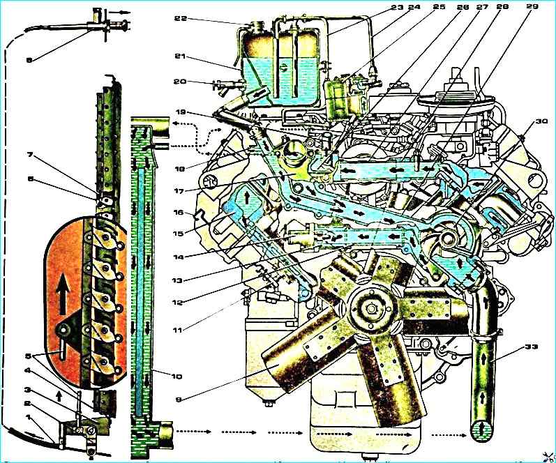
Cooling system diagram: 9 - fan impeller; 10 - radiator; 11 - cooling system drain cock; 12 - right half-block inlet pipe; 13 - inlet pipe branch pipe; 14 fan drive fluid coupling switch; 15 - cylinder head; 16 - drain cock handle; 17 - thermostat box; 18 - coolant drain pipe from expansion tank to water pump; 19 coolant drain pipe to heater; 20 - coolant level control valve, 21 - expansion tank; 22 - steam lock; 23 - bypass pipe; 30 - water pump
The liquid from the pump is pumped into the cooling cavity of the left bank of cylinders, and through the pipe into the cooling cavity of the right bank of cylinders.
Washing the outer surfaces of the cylinder liners, the coolant enters the cooling cavities of the cylinder heads through the holes in the upper mating surfaces of the cylinder block.
From the cylinder heads, the heated liquid enters the thermostat box through the pipes, from which, depending on the temperature, it is directed to the radiator or to the pump inlet.
Part of the liquid is diverted from the branch pipe to the water-oil heat exchanger, in which heat is transferred from the oil to the coolant.
From the heat exchanger, the liquid is directed to the water jacket of the cylinder block in the area of the fourth cylinder.
The temperature of the coolant at the outlet of the engine should be maintained within 85-90 °С.
The engine thermal mode is automatically regulated by thermostats and a fan drive fluid coupling switch, which control the direction of fluid flow and fan operation depending on the coolant temperature at the engine inlet.
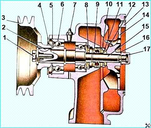
The centrifugal water pump is installed on the front part of the cylinder block on the left.
The shaft rotates in bearings and with a one-sided rubber seal.
A rubber cuff is installed for additional protection against coolant penetration into the bearings.
The seal prevents coolant from leaking out of the pump cavity.
The seal is pressed into the pump body, and its graphite ring is constantly pressed by a spring to the thrust steel ring.
A sealing rubber ring in a thin-walled brass cage is installed between the thrust ring and the impeller.
High quality workmanship of the ends of the graphite and thrust rings ensures reliable contact sealing of the pump cavity.
During periodic operation (during seasonal maintenance) it is necessary to replenish the Litol-24 grease using a grease nipple until it appears from the inspection hole.
There is a drain hole in the pump body to check the serviceability of the end seal.
Liquid leakage through this hole indicates a malfunction of the pump seal.
Clogging of the hole is not allowed, as it leads to failure of the bearings.
An axial fan, metal, five-bladed, with a diameter of 660 mm is attached with four bolts to the hub of the driven shaft of the fluid coupling.
With a fan of the engine mod. 740.10 are not interchangeable.
The fan casing helps to increase the efficiency of the fan.
The casing is made by stamping from thin sheet metal.
The radiator is four-row, to improve heat transfer, the cooling tapes are made with louvered cuts, it is attached with side brackets through rubber pads to the frame side members, and with a lower rod to the first cross member of the frame.
The radiator louvers are installed in front of the radiator.
The louvers are controlled by the drive rod handle located on the instrument panel.
With the louver handle fully recessed, and open, when fully extended - closed.
The blinds help to accelerate the engine warming up when starting, and maintain the engine thermal mode at low ambient temperatures.
The expansion tank is installed on the engine on the right side along the vehicle and is connected by a bypass pipe to the water pump inlet, a steam-air tube to the upper radiator tank and a pipe for draining liquid from the compressor.
The expansion tank is used to compensate for changes in the volume of the coolant when it expands from heating, and also allows you to control the degree of filling of the cooling system and helps remove air and steam from it.
The expansion tank is made of translucent propylene copolymer.
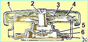
Expansion tank cap: 1 - cap body; 2 - valve stand; 3 - spring; 4 - cap spring; 5 - outlet valve; 6 - inlet valve; 7 - gasket
The expansion tank cap with inlet (air) and outlet (steam) valves is screwed onto the tank neck.
The outlet valve, loaded with a spring, maintains excess pressure in the cooling system up to 65 kPa (0.65 kgf/cm 2), the inlet valve, loaded with a weaker spring, prevents the creation of a vacuum in the system when the engine cools down.
The inlet valve opens and communicates the cooling system with the environment when the vacuum in the cooling system is 1-13 kPa (0.01-0.13 kgf/cm 2).
Operation of the car without the expansion tank cap is not allowed.
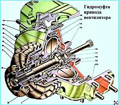
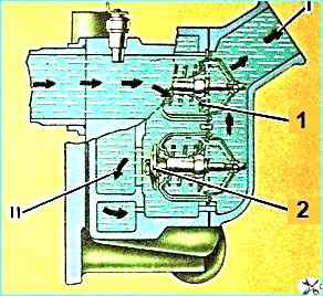
The fan drive fluid coupling (see figure) transmits torque from the crankshaft to the fan and dampens inertial loads that occur when the crankshaft speed changes abruptly.
The fluid coupling is located coaxially with the crankshaft.
The front block cover and the bearing housing are connected with screws and form a cavity in which the fluid coupling is installed.
The drive shaft assembled with the casing, the drive wheel, the shaft and the pulley, connected with bolts, make up the leading part of the fluid coupling, which rotates in ball bearings.
The leading part of the fluid coupling is driven from the crankshaft through a splined shaft.
The driven wheel assembled with the shaft, on which the fan hub is fixed, make up the driven part of the fluid coupling, rotating in ball bearings. The fluid coupling is sealed with rubber cuffs.
Radial blades are cast on the inner toroidal surfaces of the driving and driven wheels.
There are 33 of them on the driving wheel, and 32 on the driven wheel. The interblade space of the wheels forms the working cavity of the fluid coupling.
Torque is transmitted from the driving wheel of the fluid coupling to the driven wheel when the working cavity is filled with oil.
The rotation speed of the driven part depends on the amount of oil entering the fluid coupling.
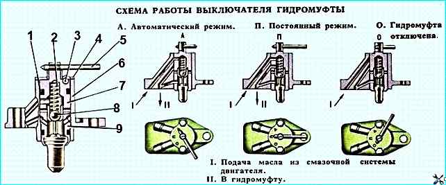
The fluid coupling switch controls the operation of the fan drive fluid coupling.
Oil flows into the fluid coupling through it.
The switch is installed in the front part of the engine on the pipe supplying coolant to the right row of cylinders.
The switch has three fixed positions and ensures the operation of the fan in one of the modes:
- automatic - the switch lever is set to position "A" (see figure).
When the temperature of the coolant washing the thermal power sensor (Fig. Fluid coupling switch) increases, the active mass located in its cylinder begins to melt, which, increasing in volume, moves the sensor piston and the ball.
At a liquid temperature of 86-90 ° C, the ball opens an oil channel in the housing switch.
Oil from the main engine line through channels in the switch housing, the block and its front cover, the tube and channels in the drive shaft enters the working cavity of the fluid coupling.
In this case, the torque from the crankshaft is transmitted to the fan impeller.
When the coolant temperature is below 86 °C, the ball, under the action of the return spring, closes the oil channel in the housing, and the oil supply to the fluid coupling stops.
In this case, the oil in the fluid coupling drains through the hole in the casing into the engine crankcase and the fan is switched off;
- the fan is switched off - the switch lever is set to the "O" position (Fig.)
Position of the fan drive fluid coupling switch): oil is not supplied to the fluid coupling, while the impeller can rotate at a low frequency under the action of friction forces arising from the rotation of the bearings and fluid coupling cuffs;
- the fan is on constantly – the switch lever is set to the "P" position; in this case, oil is supplied to the fluid coupling constantly, regardless of the coolant temperature, the fan blades rotate constantly at a frequency approximately equal to the engine crankshaft speed.
The main operating mode of the fluid coupling is automatic.
If the fluid coupling switch fails in automatic mode (characterized by engine overheating), it is necessary to switch the fluid coupling to constant mode (set the switch lever to the "I" position) and, as soon as possible, eliminate the switch malfunction.
Thermostats (see figure) with a solid filler and a direct valve stroke are designed to automatically regulate the engine's thermal mode, located in a box (Fig. Cooling system diagram), fixed to the front end of the right row of the cylinder block.
When the engine is cold, the liquid inlet to the radiator is blocked by a valve, and the inlet to the bypass pipe to the water pump is open by a valve.
The coolant circulates, bypassing the radiator, which accelerates engine warm-up.
When the coolant temperature reaches 80 ° C, the active mass contained in the cylinder melts, increasing in volume, and squeezes out the rod.
In this case, the cylinder valve, and the valve closes the liquid inlet to the bypass pipe to the water pump.
The coolant begins circulate through the radiator.
In the temperature range of 80-93°C, the valves are partially open, the coolant passes through the radiator and the bypass pipe to the pump inlet.
At a temperature of 93°C, the valve opens completely, and the other valve closes, while all the liquid circulates only through the radiator.
When the coolant temperature drops to 80°C and below, the volume of the active mass decreases and the valves, under the action of the thermostat springs, take their original position.
The coolant temperature in the system is monitored by the indicator on the instrument panel.
When the temperature in the cooling system rises to 98-104°C, the coolant overheating emergency indicator lamp lights up on the instrument panel.
Cooling system maintenance
The engine is filled with coolant through the filler neck of the expansion tank.
Before filling the cooling system, it is necessary first open the heating system tap.
The fluid level is checked visually on a cold engine.
The normal level should be between the "MIN" and "MAX" marks on the side surface of the tank.
To drain the coolant, open the drain valves of the lower elbow of the water pipeline, the heat exchanger and the pump unit of the pre-heater, the supply pipe of the cabin heater and unscrew the cap of the expansion tank.
Adjusting the tension of the water pump drive belts is described in the article - Replacing the drive belts of the generator and water pump Kamaz.
")

")
")
")
")
")
")
")