Adjusting lever (ratchet) of a KamAZ vehicle
The adjusting lever is designed to reduce the gaps between the pads and the brake drum, which increase due to wear of the friction linings.
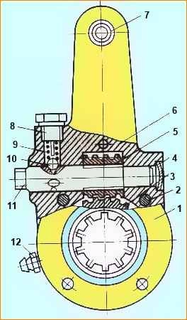
Fig.1. Adjustment lever: 1 - cover, 2 - rivet, 3 - gear, 4 - plug, 5 - worm, 6 - body, 7 - bushing, 8 - lock bolt, 9 - lock spring, 10 - lock ball , 11 - worm axis, 12 - oiler
The adjusting lever has a steel body (Fig. 1) with a bushing 7; the housing contains a worm gear with a spline hole for installing it on the expansion fist and a worm 5 with an axis 11.
To fix the worm axis there is a locking device, the ball 10 of which fits into the holes on the worm axis 11 under the action of a spring 9 resting on a bolt 8 with a stop.
Gear 3 is kept from falling out by covers 1 attached to the lever body 6.
When the axle is turned (by the square end), the worm turns the wheel, and with it the expansion cam, pushing the pads apart and reducing the gap between the pads and the brake drum.
When braking, the adjustment lever is turned by the brake chamber rod.
Before adjusting the gap, turn out the locking bolt 8 by 1-2 turns, thereby moving the stop away from the ball; after adjustment, tighten the bolt 8 securely.
During maintenance, you need to check that the axis of the adjustment lever rotates freely, without jamming.
Otherwise, you need to wash the inner cavity of the lever with gasoline, dry the adjustment lever and fill it with fresh lubricant.