The valve timing mechanism is designed to ensure the intake of fresh air into the cylinders and the exhaust of exhaust gases from them
The intake and exhaust valves open and close in certain positions of the piston, which is ensured by aligning the marks on the drive gears of the units during their installation.
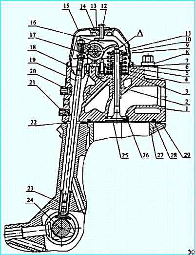
Valve timing mechanism: 1 - cylinder head; 2 - guide bushing; 3 - valve spring washer; 4, 5 - valve springs; 6 - valve cuff; 7 - washer; 8 - head fastening bolt; 9 - spring plate; 10 - spring plate bushing; 11 - valve cracker; 12 - cover fastening bolt; 13 - washer; 14 - vibration-isolating washer; 15 - cylinder head cover; 16 - valve rocker arm; 17 - rocker arm stand; 18 - cover gasket; 19 - rod; 20 - intake manifold fastening insert; 21 - water pipe fastening insert; 22 - sealing gasket; 23 - tappet; 24 - camshaft; 25 - exhaust valve; 26 - exhaust seat; 27 - cylinder liner; 28 - gas joint ring; 29 - cylinder block; (A) - thermal clearance.
Gas distribution mechanism - overhead valve with lower camshaft location.
Camshaft cams 24 in accordance with the valve timing phases actuate tappets 23.
Rods 18 impart a rocking motion to rocker arms 16, and they, overcoming the resistance of springs 7 and 8, open valves 25.
The valves close under the action of the compression force of the springs.
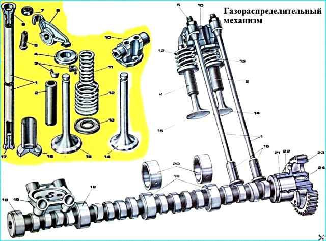
Timing mechanism: 1 - valve tappet rod; 2 - valve guide bushings; 3 - spring plate fastening crackers; 4 - spring plate; 5 - adjusting screw; 6 - upper rod end; 7 - nut; 8 - valve rocker arm; 10 - rocker arm stand; 11 - inner valve spring; 12 - outer valve spring; 13 - spring washer; 14 - exhaust valve; 15 - intake valve; 16 - valve tappet; 17 - lower rod end; 18 - camshaft bearing journals; 19 - tappet guide; 20 camshaft journal bushings; 21 - camshaft rear bushing; 22 - bearing housing; 23 - camshaft gear; 24 - key
The camshaft is made of steel, the cams and bearing journals are heat treated with high-frequency current; it is installed in the collapse of the cylinder block on five plain bearings, which are steel bushings filled with an antifriction alloy.
The diameter of the bushings is 6 mm larger compared to the bushings of the engine mod. 740.10.
The camshaft has increased dimensions, modified valve timing and valve lift compared to the camshaft of the engine mod. 740.10.
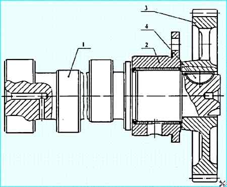
Camshaft: 1 - camshaft; 2 - bearing housing; 3 - gear; 4 - key
A straight-toothed gear 3 is pressed onto the rear end of the camshaft.
The camshaft is driven from the crankshaft gear through the intermediate gears.
The gears are steel, stamped with heat-treated teeth.
To ensure the specified valve timing, the gears are installed during assembly according to the marks stamped on the ends (see the article "Technical characteristics of the KAMAZ 740.11-240 engine").
The shaft is secured from axial movement by the housing 2 of the rear support bearing, which is fastened to the cylinder block with three bolts.
The landing diameter of the rear support bearing housing is larger compared to the bearing housing of the engine mod. 740.10.
Installation of the bearing housing of the rear support of the camshaft of the engine mod. 740.10 is not allowed, as it will lead to an emergency decrease in oil pressure in the system and premature failure of the engine.
Valves made of heat-resistant steel.
The angle of the working chamfer of the valves is 90°. The diameter of the inlet valve plate is 51.6 mm, the outlet valve - 46.6 mm, the lift height of the inlet valve is 14.2 mm, the outlet valve - 13.7 mm.
The geometry of the inlet and outlet valve plates ensures the corresponding gas-dynamic parameters of the intake and exhaust of gases and therefore their replacement with valves of the engine mod. 740.10 is not recommended.
The valves move in guide bushings made of metal ceramics.
To prevent oil from entering the cylinder and reduce its consumption through burning, rubber sealing cuffs are installed on the valve guides.
To The rockers are of the disc type with a profiled guide part, made of steel with subsequent surfacing of the disc surface with chilled cast iron.
The tappet has been subjected to chemical-thermal treatment.
The valve rocker arms are steel, stamped, and are a two-arm lever, in which the ratio of the large arm to the small one is 1.55.
The rocker arms of the intake and exhaust valves are installed on a common stand and fixed in the axial direction with a spring retainer.
The rocker arms of the 740.11-240 engine, unlike the rocker arms of the 740.10 engine, do not have a bronze bushing.
The tappet guides are cast integrally with the cylinder block.
The tappet rods are steel, hollow with pressed-in tips. The rods are 3 mm shorter than the rods of the engine mod. 740.10 and are not interchangeable with them.
The rocker arm stand is made of cast iron, its journals are subjected to heat treatment with high-frequency current.
The diameter of the journals is 2 mm larger compared to the journals of the rocker arm stand of the engine mod. 740.10.
The valve springs are helical, two are installed on each valve.
The springs have different winding directions. The wire diameter of the outer spring is 4.8 mm, the inner one is 3.5 mm.
The pre-set spring force is 355 N, the total working force is 821 N. The springs are interchangeable with the springs of the engine mod. 740.10.
The procedure for adjusting the clearances between the rocker arm noses and the valves is described in the "Maintenance" section.
Cylinder heads 1 (Fig. 1) are separate for each cylinder, made of aluminum alloy. The cylinder head has a cooling cavity communicating with the cooling cavity of the block.
To strengthen the bottom of the head, its thickness is increased in the area of the exhaust channel and an additional rib is made compared to the cylinder head of the engine mod. 740.10.
Each cylinder head is installed on two mounting pins pressed into the cylinder block, and is secured with four bolts made of alloy steel.
One of the mounting pins simultaneously serves as a sleeve for supplying oil for lubricating the valve rocker arms. The bushing is sealed with rubber rings.
In comparison with the 740.10 engine head, the head has a larger hole for draining engine oil from under the valve cover into the rod cavity.
The inlet and outlet channel windows are located on opposite sides of the cylinder head.
The inlet channel has a tangential profile to ensure optimal rotational movement of the air charge, which determines the parameters of the working process and environmental performance of the engine, so replacement with cylinder heads of the 740.10 engine is not allowed.
Cast iron seats and metal-ceramic valve guides are pressed into the head.
The valve seats have an increased interference fit compared to the seats of the engine mod. 740.10, and are fixed with a sharp edge.
The exhaust seat and valve are profiled to provide less resistance to exhaust gas release.
Use of the exhaust valve mod. 740.10 is not recommended.
The joint "cylinder head - liner" (gas joint) is gasketless (Fig. Gas joint).
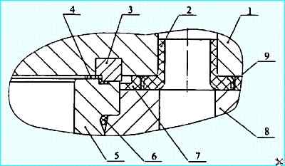
Gas joint: 1 - cylinder head; 2 - coolant bypass sealing ring; 3 - gas joint ring; 4 - filler gasket; 5 - cylinder liner; 6 - sealing ring; 7 - sealing gasket; 8 - cylinder block: 9 - screen
A steel sealing ring 3 is pressed into the bored groove on the lower plane of the head. By means of this ring, the cylinder head is installed on the liner flange.
The tightness of the seal is ensured by high precision machining of the mating surfaces of the sealing ring and the cylinder liner 5.
The sealing ring additionally has a lead coating to compensate for microroughness of the sealed surfaces.
A fluoroplastic gasket - filler 4 is installed in the gas joint to reduce harmful volumes.
The gasket - filler is fixed on the protruding belt of the gas joint ring due to the reverse cone with tension.
The use of the filler gasket reduces the specific fuel consumption and smoke of the exhaust gases. Disposable filler gasket.
To seal the coolant bypass channels, silicone rubber sealing rings 2 are installed in the holes in the bottom of the head.
The space between the head and the block, the engine oil drain holes and the rod passage holes are sealed with a cylinder head gasket 7 made of heat-resistant rubber.
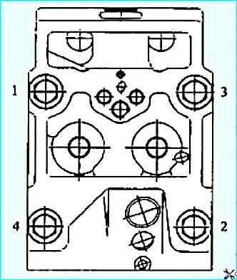
Tightening sequence of cylinder head bolts
When assembling the engine, the cylinder head bolts should be tightened in three stages in the ascending order of numbers shown in Fig. 5
The tightening torque values should be:
- Step 1 - up to 39-49 Nm (4-5 kgf.m);
- Step 2 - up to 98-127 Nm (10-13 kgf.m);
- Step 3 - up to 186-206 Nm (19-21 kgf.m
Before screwing in, lubricate the bolt threads with a layer of graphite grease.
After tightening the bolts, it is necessary to adjust the clearances between the valves and rocker arms adjusting the valve clearances is described in the article - General information on maintenance of the Kamaz engine.
The valve mechanism is covered with an aluminum cover 15 (see Fig. 1).
For noise insulation and sealing of the joint, the cover - The cylinder head uses a vibration-isolating washer 14 and a rubber sealing gasket 19.
Tighten the cylinder head cover mounting bolts with a torque of 12.7-17.6 Nm (1.3-1.8 kgf.m).
Main faults of the valve timing mechanism
Deviations in the operation of the valve timing mechanism during natural wear of parts cause deterioration in the dynamics of the mechanism and contribute to accelerated wear of the mating parts. Of the total number of failures of all engine systems, 25-27% are due to timing belt failures.
The main engine failures caused by timing belt failures may be the following:
- - decreased engine power, increased fuel and oil consumption;
- - increased exhaust smoke;
- - decreased oil pressure in the engine system at temperatures above 0° C;
- - unstable engine operation at idle;
- - engine operation with interruptions or overheating;
- - fluid leaks in the connections of the cooling system.
Signs of timing belt failures are knocking in the cylinder head.
A ringing knock in the cylinder head is caused by the valves knocking on the rocker arms due to the large thermal gap between the valve and the nose rocker arms.
A dull metallic knock at idle and its intensification when fuel is supplied are a sign of broken valve springs or jammed valves.
A loose fit of the valve on the seat occurs when there is no or a decrease in the thermal gap between the rocker arm tip and the valve, as well as when the load-bearing capacity of the fixed connection between the cylinder head and the valve seat is violated.
When the valve does not fit tightly on the seat, gaps are formed in certain areas between the valve and the seat.
Hot gases under pressure and at high speed pass into the formed cracks, so the chamfer surfaces in this place corrode intensively, and the fit of the chamfer to the seat deteriorates.
Combustion products accumulate on the chamfer surface, as a result of which the tightness of the connection is broken.
Analysis of typical damage to valves and their seats shows that Approximately 90% of all damage occurs when the tightness of the seat-valve connection is broken.
As the thermal clearance increases, the valve lift decreases, which results in poor filling and cleaning of the cylinders, increased impact loads and wear of the timing parts.
With very small thermal clearances, as a result of combustion or wear of the working chamfers of the valve or valve seat, the tightness of the combustion chamber is not ensured, the engine loses compression, overheats and does not develop full power.
The most common timing faults are as follows:
- – premature wear of the seat and valve seat seating surfaces; valve guide wear;
- – instability of the fit in the valve seat - cylinder head mating;
- – deformation of the cylinder head;
- – deformation of the valve seat and stem;
- – deformation of the valve plate; breakage of the valve stem and corrosion; wear of the tappet holes;
- – wear of the camshaft bushings; wear of the camshaft cams; wear of valve rocker arms.
Before performing maintenance, individual monitoring of the timing belt condition is required, which allows, using special equipment, without disassembling the engine, to identify the above-mentioned hidden faults in advance and determine the list of preventive and repair actions.
The technical condition of the timing belt should be assessed based on diagnostic parameters, and the need for maintenance and repair operations should be determined based on the limit values of these parameters.
A typical defect of the rods: loose fit of the tips and bending of the rod rod.
Typical defects of the valves are wear of the working chamfers, bending of the rod, breakage of the valve plate, wear of the valve end face
Typical defects of the tappets are wear of the plate, cavities on the working surface, wear of the rod
Worn plates and rods of the tappets are restored chrome plating.
After restoration, the valves are ground into their seats cylinder dexterity.
")

")
")
")
")
")
")
")