Turbochargers of diesel engines KAMAZ 740.11-240, 740.13-260, 740.14-300
The gas turbine supercharging system, by using part of the energy of the exhaust gases, provides the supply of pre-compressed air to the engine cylinders
Supercharging allows to increase the density of the air entering the cylinders, to burn more fuel in the same working volume and, as a result, to increase the liter power of the engine.
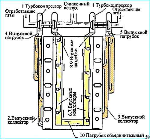
The engine's gas turbine supercharging system consists of two interchangeable turbochargers, exhaust and intake manifolds and pipes (see figure).
Turbochargers are installed on the outlet manifolds, one for each row of cylinders.
The outlet manifolds and pipes are made of high-strength cast iron VCh50.
The gas joints between the mounting flanges of the turbocharger turbine, outlet pipes and manifolds are sealed with heat-resistant steel gaskets.
The gaskets are single-use parts and are subject to replacement during system overhauls.
The gas joint between the outlet manifold and the cylinder head is sealed with a gasket made of asbestos-steel sheet edged metal plated tape
The exhaust manifolds are made of one piece, attached to the cylinder heads with bolts and secured with lock washers.
To compensate for angular movements of the exhaust manifold mounting bolt head that occur when heated, a special spherical washer is installed under the bolt head.
The intake manifolds and pipes are made of cast aluminum alloy AK9ch and are connected to each other with bolts.
The joints between the manifolds and pipes are sealed with paronite gaskets.
To equalize the pressure between the two rows of cylinders, the intake manifolds are connected by a connecting pipe.
The engine turbocharging system must be hermetically sealed.
If the exhaust tract is not hermetically sealed, the turbocharger rotor speed decreases, and, consequently, the amount of air pumped into the into the cylinders, which leads to an increase in the thermal stress of the parts, a decrease in the power and service life of the engine.
A leaky intake tract also leads to the above-mentioned disadvantages and "dust" wear of the cylinder-piston group, and therefore premature engine failure.
Turbocharger bearings are lubricated from the engine lubrication system through fluoroplastic tubes with a metal braid.
Oil is drained from the turbochargers through steel tubes into the engine crankcase. The drain pipes are connected to each other by a rubber sleeve, which is pulled together with clamps.
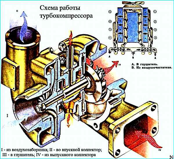
Air enters the centrifugal compressor from the air cleaner, is compressed and supplied under pressure to the engine intake pipe.
The compressor outlet pipe and the manifold inlet pipe are connected to each other by a heat-resistant rubber sleeve, which is pulled together with clamps.
The engines are equipped with a TKR7N-1, TKR7S-9 turbocharger (Fig. TKR 7S turbocharger, TKR 7N turbocharger) or its foreign analogue S2B/7624TAE/1.00 D9 from Schwitzer.
The TKR7S-9 and TKR7N-1 turbochargers are modifications of the basic models of the TKR7S and TKR7N turbochargers, respectively.
The text and figures provide descriptions and images of the basic models, which are common to all TKR modifications.
The TKR7S-9 turbocharger consists of a centripetal turbine and a centrifugal compressor, connected to each other by a bearing node.
A turbine with a two-pass housing 7 made of high-strength cast iron VCh40 converts the energy of the exhaust gases into the kinetic energy of the turbocharger rotor rotation, which is then converted into air compression work in the compressor stage.
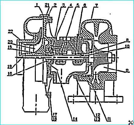
Turbocharger TKR7S: 1 - compressor housing; 2 - cover; 3 - bearing housing; 4 - thrust bearing; 5 - bearing; 6 - ring locking pin; 7 - turbine housing; 8 - sealing ring; 9 - turbine wheel; 10 - rotor shaft; 11 - turbine screen; 12 - bar; 13 - bolt; 14 - oil drain screen; 15 - bushing; 16 - oil deflector; 17 - bar; 18 - bolt; 19 - nut; 20 - compressor wheel; 21 sealing ring; 22 - diffuser
The TKR7S turbocharger rotor consists of a turbine wheel 9 with a shaft 10, a compressor wheel 20, an oil deflector 16 and a sleeve 15, secured to the shaft with a nut 19.
The turbine wheel is cast from a heat-resistant alloy using investment models and is friction welded to the steel shaft.
The compressor wheel with blades curved backwards in the direction of rotation is made of aluminum alloy and after mechanical processing is dynamically balanced to a value of 0.4 g.mm.
The bearing journals of the rotor shaft are hardened by high-frequency current to a depth of 1-1.5 mm to a hardness of 52-57 HRC3.
After mechanical processing, the rotor is dynamically balanced to a value of 0.5 g.mm.
The bushing, oil deflector, compressor wheel are installed on the rotor shaft and tightened with a nut with a torque of 7.8-9.8 Nm (0.8-1 kgf.m).
After assembly, the rotor is not additionally balanced, only the radial runout of the shaft journals is checked.
If the radial runout value is no more than 0.03 mm, marks are applied to the rotor parts in one plane and the rotor is allowed to assemble the turbocharger.
When installing the rotor on the bearing housing, it is necessary to align the marks on the rotor parts.
The rotor rotates in bearings 5, which are floating rotating bushings.
The axial movements of the rotor are limited by thrust bearing 4, clamped between the bearing housing 3 and cover 2. The bearings are made of bronze BrO10S10.
The turbocharger bearing housing is made of a composite cast iron housing VCh50 and an aluminum alloy cover in order to reduce heat transfer from the turbine to the compressor.
A heat-resistant steel screen 11 is installed between the turbine housing and the bearing housing to reduce heat transfer.
An oil-sweeping screen 14 is installed in the bearing housing, which, together with elastic split rings 8, prevents oil leakage from the housing cavity.
A rubber sealing ring 21 is installed to eliminate air leaks in the "compressor housing - bearing housing" connection.
The turbine and compressor housings are attached to the bearing housing using bolts 12, 17 and strips 13, 18.
This design allows them to be installed at any angle to each other, which in turn facilitates installation of turbocharger on the engine.
Turbocharger TKR7N
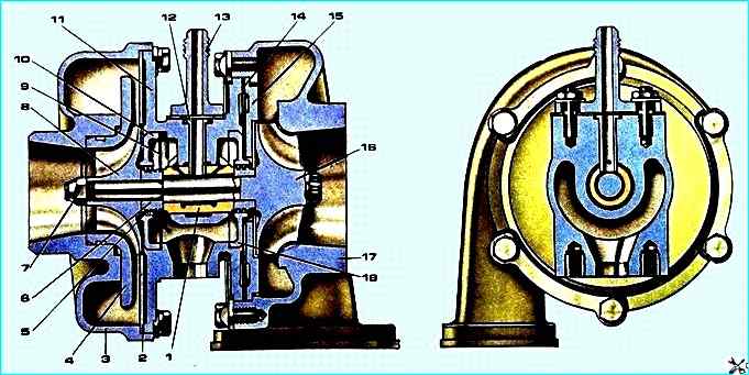
Turbocharger TKR7N: 1 - bearing; 2 - screen; 3 - sealing rings; 6 - housing nut; 7 - compressor; 4 - diffuser; 5, 18 - oil deflector; 8 - compressor wheel; 9 - oil drain screen; 10 - cover; 11 - bearing housing; 12 - retainer; 13 - adapter, 14 - gasket; 15 - turbine screen; 16 - turbine wheel; 17 - turbine housing
Unlike the TKR7S turbocharger, the TKR7N turbocharger design uses an isobaric single-pass turbine housing and a swing-type bronze mono-bushing as a bearing.
The turbocharger rotor consists of a turbine wheel with a shaft 16, a compressor wheel 8 and an oil deflector 7, secured to the shaft with a nut 6.
The rotor rotates in a bearing 1, which is held from axial and radial movement by a lock 12, which, together with an adapter 13, is also an oil supply channel.
Steel covers 10 and an oil drain screen 9 are installed in the bearing housing 11, which, together with elastic split rings 5, prevents oil leakage from the housing cavity. bearing.
To reduce heat transfer from the turbine housing to the bearing housing, a cast iron screen 15 and two steel gaskets 14 or a cast iron screen 15 and an edged asbestos-steel gasket 14 are installed between them.
Due to the fact that the turbocharger rotor is balanced with high precision, complete disassembly and maintenance of the unit must be carried out at specialized enterprises with the necessary equipment, tools and devices.
The 740.11-240 engine is equipped with a TKR7N-1 or TKR7S-9 turbocharger
The 740.13-260 and 740.14-300 engines are equipped with an S2B/7624TAE/1.00 D9 turbocharger
Technical characteristics of the turbocharger TKR7S-9
Air supply range through the compressor, kg/sec: 0.05-0.2
Boost pressure (excess) at rated engine power, kPa (kgf/cm 2), not less than: 80 (0.8)
Rotor speed at rated engine power, rpm: 90000-100000
Turbine inlet gas temperature, K (°C)
- - permissible during 1 hour: 1023 (750)
- - permissible without time limitation: 973 (700)
Pressure (excess) of lubricating oil at the turbocharger inlet, at an oil temperature of 80-95 °C, kPa (kgf / cm 2)
- - at the nominal speed of the engine crankshaft: 294-442 (3.0-4.5)
- - at the minimum speed of the engine crankshaft, not less than: 98 (1.0)
Technical characteristics of the TKR7N-1 turbocharger
Range of air supply through the compressor, kg / sec: 0.05-0.18
Boost pressure (excess) at rated engine power, kPa (kgf/cm2), not less than: 60 (0.6)
Rotor speed at rated engine power, rpm: 80000-90000
Turbine inlet gas temperature, K (°C)
- - permissible for 1 hour: 973 (700)
- - permissible without time limit: 923 (650)
Pressure (excess) of lubricating oil at turbocharger inlet, at oil temperature of 80-95 °C, kPa (kgf/cm 2)
- - at rated engine crankshaft speed: 294-442 (3.0-4.5)
- - at minimum engine crankshaft speed, not less than: 98 (1.0)
Technical characteristics of turbocharger S2B/7624TАЕ/1.00D9
Air supply range through compressor, kg/sec: 0.05-0.22
Boost pressure (excess) at rated engine power, kPa (kgf/cm 2), not less than: 110(1.1)
Rotor speed at rated engine power, rpm: 90000-100000
Turbine inlet gas temperature, K (°C)
- - permissible for 1 hour: 1023 (750)
- - permissible without time limitation: 973 (700)
Pressure (excess) of lubricating oil at the turbocharger inlet, at an oil temperature of 80-95 °C, kPa (kgf/cm 2)
- - at the rated engine crankshaft speed: 294-442 (3.0-4.5)
- - at the minimum engine crankshaft speed, not less than: 98 (1.0)
Recommended operating modes of a turbocharged engine
To avoid oil being sucked in from turbochargers and getting into engine cylinders, onto the flow parts of the compressor and turbine, it is not recommended to operate for a long time, more than 10 minutes, engine operation at idle speed with a crankshaft speed of less than 700 min -1.
This leads to coking of the piston rings, contamination of the compressor flow path and carbon formation on the turbine flow path.
When the engine is forced to operate at idle speed (warming up, pumping air into the brake system cylinders, etc.), it is necessary to maintain the crankshaft speed of at least 1000-1200 min -1.
Before stopping the engine after its operation under load, it is necessary to set the idle mode for at least 3 minutes to avoid overheating of the turbocharger bearing and coking of the rotor.
Sudden engine stop after operation under load is prohibited.
Loss of power, smoking, high fuel consumption, engine overheating, high exhaust temperature, oil leaks from the turbocharger - these are symptoms of malfunctions in the systems associated with turbocharging.
However, all this is often unfairly attributed to a turbocharger malfunction, since defects in other engine parts lead to similar symptoms.
Since the turbocharger is a self-adjusting engine unit, only mechanical malfunctions or blockage of air and gas channels due to dirt and foreign objects impair its operation.
Before stopping the engine after its operation under load, it is necessary to set the idle mode for at least 3 minutes to avoid overheating of the turbocharger bearing and coking of the rotor.
Suddenly stopping the engine after operation under load is prohibited.
Repair turbocharger
If the seal between the turbine mounting flange and the manifold outlet pipe is broken, replace the steel gasket.
If extraneous noises appear, as well as increased smoking and a decrease in engine power associated with the technical condition of the turbocharger, disconnect the exhaust pipe from the turbocharger and check the ease of rotation of the rotor.
If the rotation is difficult, jammed or the rotor touches the housing parts, remove the turbocharger.
Remove the turbocharger in the following sequence:
- - remove the air cleaner (when removing the left turbocharger), connecting pipes, tee;
- - disconnect the oil supply pipe to the turbocharger;
- - loosen the clamps securing the connecting pipes of the housing compressor;
- - unlock and unscrew the bolts of the exhaust manifold, move the exhaust manifold back, disconnect the oil drain line, remove the exhaust manifold from the turbocharger assembly.
Note. For for ease of subsequent installation, before disassembling the turbocharger, apply marks to the bearing housing on the turbine and compressor housings to indicate their mating with the bearing housing;
- - unscrew the six turbine mounting bolts and remove the compressor housing together with the bearing housing;
- - unscrew the eight compressor housing mounting bolts and remove it;
- - wash the compressor housing and screen in diesel fuel, remove deposits;
- - wash the bearing housing from the compressor side and remove deposits from the surfaces of the blades and housing.
Attention! To avoid damaging the surfaces of the blades and disrupting the rotor balance, do not use metal objects to remove deposits or correct bent blades;
- check the integrity of the wheel blades and the absence of bends on them. If there are damaged blades, replace the turbocharger.
Attention! Since the turbocharger rotor is balanced with high precision during assembly, disassembly of the turbocharger rotor is not allowed.
Complete disassembly of the turbocharger is carried out at specialized enterprises that have the necessary equipment and devices;
- - assemble the turbocharger in the reverse order. Install the compressor and turbine housings relative to the bearing housing using the marks;
- - tighten the compressor housing mounting bolts with a torque of 4.9-7.8 Nm (0.5-0.8 kgf.m), the turbine housing mounting bolts with a torque of 23.5-29.4 Nm (2.4-3.0 kgf.m);
- - check the ease of rotation of the rotor and the absence of its contact with the housing parts at its extreme axial and radial positions;
- - install the exhaust manifold, tighten the mounting bolts with a torque of 43.1-54.9 Nm (4.4-5.6 kgf.m), lock the bolts.
Possible turbocharging malfunctions and troubleshooting methods
Malfunction
- cause malfunctions
Troubleshooting
Loss of engine power, black smoke
- dirty air filter
Clean or replace air filter
- obstruction of air supply to turbocharger compressor
Remove obstruction or replace defective parts
- leak in air supply line to turbocharger compressor
Tighten clamp bolts, replace sleeves if necessary
- leak in air outlet line from turbocharger compressor to intake system
Tighten clamp bolts, replace sleeves and gaskets if necessary
Blue smoke
- coking of turbine rotor, turbocharger seal unit
Repair in specialized workshop or turbocharger replacement
- poor crankcase ventilation
Eliminate resistance, replace faulty parts if necessary
")

")
")
")
")
")
")
")