Input shaft 13 is mounted on two ball bearings.
The front bearing of the input shaft with a cuff is located in the crankshaft socket, the rear bearing is located in the bore of the front end of the gearbox housing
The rear bearing is secured against axial movements by a retaining ring installed in the groove of its outer ring.
The input shaft is integral with the gear. The front part of the shaft, which goes into a cylindrical journal under the front ball bearing, has splines.
The hubs of the driven clutch discs are installed on the shaft splines.
The input shaft gear is helical and is constantly in mesh with gear 9 of the intermediate shaft drive; has an internal ring gear designed to connect to the gear ring of the synchronizer carriage, and an internal cylindrical hole for installing the front roller bearing of the secondary shaft.
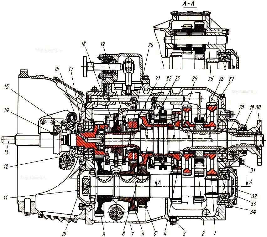
Five-speed gearbox with clutch housing assembly: 1 - first gear gear of the secondary shaft; 2 - reverse gear block; 3 - drain plug; 4 - second gear of the secondary shaft; 5 - third gear of the intermediate shaft; 6 - fourth gear of the intermediate shaft; 7 - crankcase; 8 - secondary shaft; 9 - intermediate shaft drive gear; 10 – cover of the front bearing of the intermediate shaft; 11 - intermediate shaft; 12 - ring nut for fastening the bearing; 13 - input shaft; 14 – clutch release clutch; 15 - cuff; 16 - oil injection ring; 17 - cover of the rear bearing of the input shaft; 18 – synchronizer for fourth and fifth gears; 19 - thrust washer; 20 - lock key of the thrust washer; 21 - fourth gear gear of the secondary shaft; 22 - third gear gear of the secondary shaft; 23 - synchronizer for second and third gears; 24 - reverse gear bushing; 25 – axis of the reverse gear block; 26 - reverse and first gear clutch; 27 - first gear bushing; 28 - speedometer drive worm; 29 - cuff of the secondary shaft bearing cover; 30 - flange; 31 - cover of the rear bearing of the secondary shaft; 32 - rear cover of the intermediate shaft; 33 - thrust washer; 34 – bearing cup
The rear bearing of the input shaft is pressed onto a cylindrical journal of larger diameter until it stops at the front end of the gear.
The bearing is secured against axial movements on the shaft by nut 12 through oil injection ring 16.
The nut on the shaft is cored at two points.
The oil injection ring is designed to force lubricant to the secondary shaft gear bearings.
It has a right-handed three-start screw thread on the outer surface, which pumps oil into the discharge cavity when the input shaft rotates.
The oil injection ring is secured against rotation by a ball installed in the input shaft well and inserted into the groove of the ring.
For the passage of lubricant, inclined and longitudinal holes are made in the shaft.
An oil transfer bushing is inserted into the longitudinal hole, ensuring the supply of lubricant to the longitudinal channel of the secondary shaft.
For lubricant circulation through the front bearing of the secondary shaft, radial drillings are made in the gear body.
The primary shaft assembly with the rear bearing is installed in the crankcase bore and closed with cover 17.
Adjusting gaskets are installed between the cover and the bearing, and sealing gaskets are installed between the cover and the crankcase.
Before installing the cover, two self-clamping cuffs 15 are placed in the inner cylindrical seat of a smaller diameter to prevent oil from leaking into the clutch housing.
The working edges of the cuffs have a right-hand notch, and on the cuff itself an arrow indicates the direction of shaft rotation.
The outer journal of the input shaft cover is machined to allow movement of the clutch release.
Axial forces generated during operation of the gearbox are absorbed by the rear bearing of the input shaft.
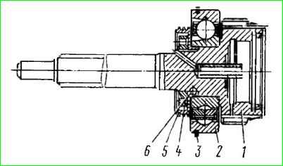
Drive shaft assembly: 1 - drive shaft; 2 - ball bearing; 3 - bearing retaining ring; 4 - ring nut; 5 - oil injection ring; 6 - locking ball
")

")
")
")
")
")
")
")