The engine operates normally only under a certain thermal condition
If cylinder heads, cylinders, pistons and all parts overheat due to contact with hot gases, wear increases due to lubricant burnout
Reducing the clearance due to thermal expansion can lead to jamming of the pistons in the cylinders.
In addition, fuel evaporates poorly, is difficult to ignite and does not burn completely, which reduces engine power and efficiency, and excessive carbon formation due to incomplete combustion of fuel can lead to stuck piston rings and stuck valves.
Wear in a supercooled engine also increases, as condensation of combustion products occurs, which, being in a liquid state, cause severe corrosion of cylinder liners, pistons and piston rings.
Due to the increase in the delay of self-ignition of the fuel, the operating severity increases.

The most favorable thermal conditions of the engine are supported by a cooling system that removes excess heat from parts and transfers it to the surrounding air.
Cooling system elements
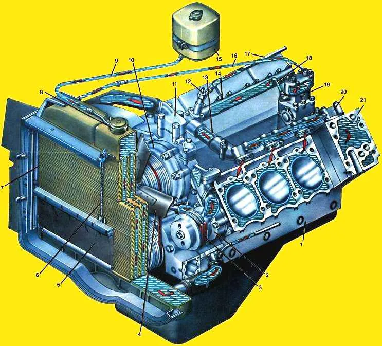
The liquid cooling system (Fig. 1.) consists of a pump 2, a fan 4 with a controlled hydraulic drive (fluid coupling of the fan drive, fluid coupling switch), a radiator with shutters, expansion tank 15, thermostats, instrumentation, cavities and channels in the cylinder block and heads, pipelines.
The cooling system is designed to withstand the most severe conditions when the engine is running at full load at high ambient temperatures.
To prevent the engine from overcooling in other, lighter operating conditions, and to ensure rapid warm-up during startup, the cooling system has control devices.
Cooling is controlled by changing the amount of air and liquid passing through the radiator.
The air flow is regulated automatically by periodically turning off the fan driven through a fluid coupling.
It is also possible to regulate the air flow by changing the position of the louvers plates, which are located in front of the radiator.
Open and close the blinds from the cab from the driver's workplace.
The amount of liquid passing through the radiator is controlled automatically by the thermostat.
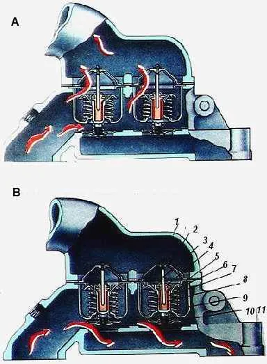
Depending on the temperature of the engine, liquid can circulate in two ways:
- in a large closed circle with the thermostat valves open (engine - radiator - warm engine)
- or in a small circle bypassing the radiator (the engine is not warmed up and the thermostat valves are closed.
The direction of movement of the coolant is shown in Figure 2 by arrows.
Thus, when the engine is running, the optimal temperature (75-98°C) of the coolant in the system is maintained automatically using thermostats and turning on the fan if necessary as follows:
At 78°C, the thermostats begin to open and the coolant partially enters the radiator; at 85-90°C the fan starts working; at 95 °C the radiator valves of the thermostats open completely and the small circle closes.

When the coolant temperature drops from 95 °C, the radiator valves of the thermostats begin to close, the bypass valves open and the coolant partially flows to the pump in a small circle, at 85 °C the oil supply to the hydraulic coupling stops and the fan is turned off, at 78 °C they close completely radiator thermostat valves and coolant does not flow into the radiator.


