A single safety valve maintains pressure in the receivers of the towing vehicle during an emergency decrease in pressure in the supply line of the trailer, and also prevents the release of compressed air from its line when the pressure in the brake drive of the towing vehicle drops, preventing automatic self-braking of the trailer.
The valve is adjusted to bypass air from port “I” to port “II” when the pressure in port “I” reaches 550 kPa.
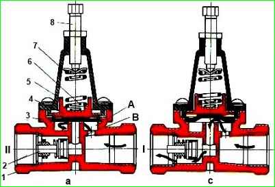
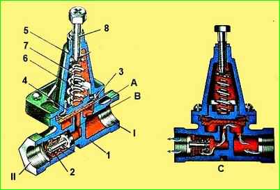
Compressed air through terminal “I” enters cavity “A” under membrane 3.
Upon reaching a pressure of 550 kPa, the compressed air, overcoming the force of springs 6 and 7, lifts the membrane 3 and passes into the sub-valve cavity “B”, from where through check valve 2 it flows to terminal “II” of the trailer supply line.
When the pressure in terminal “I” is below 545 kPa, membrane 3, under the action of springs 6 and 7, falls onto the seat and disconnects terminals “I” and “II”; in this case, check valve 2 closes and prevents the reverse movement of compressed air from terminal “II” to terminal “I”.
The valve opening pressure is set by adjusting screw 8.
When screwing it in, the valve opening pressure increases, when turning it out, it decreases.
Replacing a single safety valve
We replace the single safety valve in case of the following malfunctions:
- - violation of valve tightness. An external sign is air leakage through the terminals and at the places where the cover is attached to the valve body;
- - mechanical damage to the valve body, cover and membrane, interfering with its normal operation
Tools required: wrenches 22x24, 27x30

Removing single safety valve 28
We prepare the car and bleed air from the receivers of the 19th circuit of the parking brake system
Unscrew the union nut of the pipeline coming from the receiver 19 from the fitting of the single protective valve 28 and disconnect the pipeline from the valve
Unscrew the protective valve 28 from the tee connecting the terminal apan 27 safety valve control
Installation of a single safety valve 28
Screw the protective valve 28 onto the valve tee 27
Note: The air flow direction arrow on the single safety valve body must point towards valve 27
Connect the pipeline from the receiver 19 to the protective valve and tighten the union nut
Removing single safety valve 10
Bleeding air from receiver 19 of the parking brake system
Unscrew the union nuts of the inlet and outlet pipelines 10 from the fittings of the single safety valve
Disconnect the pipelines from the valve and remove the valve
Installation of single safety valve 10
Connect the pipelines to the protective valve 10 and tighten the union nuts of the pipelines
Note: The arrow of the single safety valve must be directed in the direction of the compressed air flow coming from the compressor
Start the engine and create pressure in the pneumatic brake drive. We check the tightness of pipelines and safety valves. Air leakage is not allowed
Disassembly and assembly of a single safety valve
Tools required: vice, soft jaws, wrench 12x13, socket wrench 10, screwdriver, special pliers I801.23.000-01, utensils for fuel and lubricant, brush
Disassembly of a single safety valve
Installing the valve in a vice
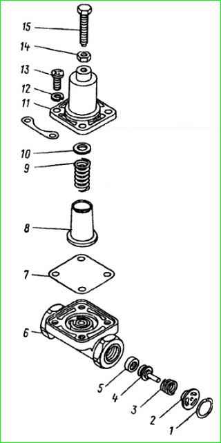
Using a 13mm wrench and a 10mm socket wrench, unscrew the adjusting screw 15 and the lock nut 14
Use a screwdriver to unscrew screws 13 of the fastening with washers 12 of the cover
Remove cover 11, spring plate 10, spring 9, piston 8, membrane 7
Remove thrust ring 1, bushing 2, spring 3, valve body 4, valve ring 5 from the body
Remove the body from the vice
We wash the valve parts in diesel fuel, blow them with compressed air and check their technical condition
Assemblyof the valve
Install valve ring 5, valve body 4, spring 3, bushing 2 and thrust ring 1 into body 6
Install into housing 6 membrane 7, piston 8, spring 9, spring plate 10
Note: cover the spring with Ciatim-221 lubricant
Install cover 11 on valve body 6, insert fastening screws 13 with spring washers into the holes of cover 11 and the body
We screw in the fastening screws 13 with spring washers 12 and screw the adjusting screw 15 into the cover, tighten the lock nut 14
Remove the valve from the vice and test the valve
Test order:
Connect the device according to the diagram
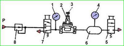
Open tap 7. Set the pressure reducer on pressure gauge 1 to 539 kPa (5.5 kgf/cm 2).
We use adjusting screw 3 to ensure that receiver 6 begins to fill. Close tap 7 and open tap 5.
Close valve 5 and open valve 7. Using gearbox 8, set pressure on pressure gauge 1 to 736 kPa (7.5 kgf/cm 2). Pressure gauges 1 and 4 should show equal pressure.
During testing, device 2 should not show a decrease in pressure
We check the adjustment again, as indicated above, and, if necessary, adjust the adjustment
")

")
")
")
")
")
")
")