KAMAZ trailer brake control valve
The trailer brake control valve with a two-wire drive is designed to actuate the brake drive of a trailer (semi-trailer) when any of the separate drive circuits of the service brake system of the tractor are turned on, as well as when the spring energy accumulators of the drive of the spare and parking brake systems of the tractor are turned on.
The valve is mounted on the tractor frame with two bolts.
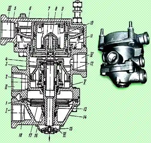
A membrane 1 is clamped between the lower 14 and middle 18 housings, which is secured between two washers 17 on the lower piston 13 with a nut 16 sealed with a rubber ring.
Attached to the lower body with two screws is an outlet window 15 with a valve that protects the device from dust and dirt.
When one of the screws is loosened, the outlet window 15 can be rotated and access to the adjusting screw 8 through the hole of valve 4 and piston 13 can be opened.
The trailer brake control valve with a two-wire drive generates a control command for the air distributor of the trailer (semi-trailer) brake system from three independent commands, acting both simultaneously and separately.
In this case, a direct action command (to increase pressure) is sent to terminals I and “III”, and a reverse action command (to drop pressure) is sent to terminal “II”.
The valve leads are connected as follows:
- "I" - with the lower section of the brake valve;
- "II" - with manually operated reverse valve;
- "III" - with the upper section of the brake valve;
- "IV" - with trailer brake control line;
- "V" - with car receiver;
- "VI" - with atmosphere.
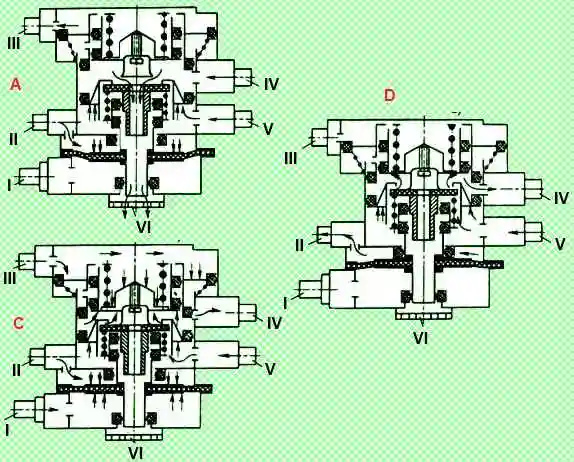
In the braked state, compressed air is constantly supplied to terminals “II” and “V”, which, acting from above on the membrane 1 and from below on the middle piston 12, holds the piston 13 in the lower position.
In this case, terminal “IV” connects the trailer brake control line with the atmospheric terminal “VI” through the central hole of valve 4 and lower piston 13.
When compressed air is supplied to terminal “III”, the upper pistons 10 and 6 simultaneously move down.
Piston 10 first sits with its seat on valve 4, blocking the atmospheric outlet in the lower piston 13, and then lifts valve 4 from the seat of the middle piston 12.
Compressed air from terminal “V” connected to the receiver flows to terminal “IV” and then into the trailer brake control line.
The supply of compressed air to terminal “IV” continues until its effect from below on the upper pistons 10 and 6 is balanced by the pressure of compressed air supplied to terminal “III” on these pistons from above.
After this, valve 4, under the action of spring 2, blocks the access of compressed air from terminal “V” to terminal “IV”.
This is how the tracking action is carried out.
When the compressed air pressure decreases at port “III” from the brake valve, i.e. when braking, the upper piston 6, under the action of the spring 11 and the pressure of compressed air from below (in terminal “IV”), moves upward along with the piston 10.
The piston seat 10 comes off the valve 4 and communicates the terminal “IV” with the atmospheric terminal “VI” through the holes of the valve 4 and piston 13.
When compressed air is supplied to terminal “I”, it enters under the membrane 1 and moves the lower piston 13 together with the middle piston 12 and valve 4 upward.
Valve 4 reaches the seat in the small upper piston 10, closes the atmospheric outlet, and with further movement of the middle piston 12 breaks away from its inlet seat.
Air comes from terminal V, connect connected with the receiver, to terminal “IV” and further into the trailer brake control line until its effect on the middle piston 12 from above is equalized by the pressure on the membrane 1 from below.
After this, valve 4 blocks the access of compressed air from terminal V to terminal "IV".
This is how the tracking action is carried out with this type of operation of the device.
When the compressed air pressure drops at port “I” and under the membrane, the lower piston 13, together with the middle piston 12, moves down.
Valve 4 comes off the seat in the upper small piston 10 and communicates terminal “IV” with atmospheric terminal VI through holes in valve 4 and piston 13.
When compressed air is simultaneously supplied to terminals “I” and “III”, the large and small upper pistons 10 and 6 move downwards, and the lower piston 13 with the middle piston 12 moves upward.
Filling the trailer brake control line through terminal “IV” and releasing compressed air from it occurs in the same way as described above.
When compressed air is released from port “II” (when braking with the spare or parking brake system of the tractor), the pressure above the membrane drops.
Under the action of compressed air from below, the middle piston 12 together with the lower piston 13 moves upward.
Filling the trailer brake control line through terminal “IV” and braking occurs in the same way as when supplying compressed air to terminal “I”.
The tracking action in this case is achieved by balancing the pressure of compressed air on the middle and piston 12 and the sum of the pressure from above on the middle and piston 12 and membrane 1.
When compressed air is supplied to terminal “III” (or when air is simultaneously supplied to terminals “III” and “I”), the pressure in terminal “IV” connected to the trailer brake control line exceeds the pressure supplied to output "III".
This ensures the advanced action of the trailer (semi-trailer) braking system.
The maximum value of excess pressure at terminal “IV” is 98.1 kPa (1 kgf/cm 2); minimum - about 19.5 kPa (0.2 kgf/cm 2), nominal - 68.8 kPa (0.6 kgf/cm 2).
The amount of excess pressure is regulated by screws 8: when the screw is screwed in, it increases, when turned out, it decreases.
Replacing the trailer brake control valve with a two-wire drive
The valve must be replaced if the following malfunctions occur:
- - violation of valve tightness. A sign is air leakage through the terminals and at the housing connectors;
- - piston jamming, membrane damage;
- - mechanical damage to the valve bodies, interfering with its operation
You will need keys 12x13, 17x19, 22x24
Removing the valve
Bleeding air from the receivers (Fig. 4) of the parking brake system
Using 17 and 22 mm wrenches, unscrew the union nuts of the pipelines connected to valve 24
Unscrew the bolts securing the bracket to the frame, disconnect the pipelines from the valve terminals and remove the valve
Unscrew the nuts securing valve 24 to the bracket
Installing the control valve
Installing the valve on the bracket
Install the valve with bracket on the frame, connect the pipelines and secure the valve
Tighten the union nuts of the pipelines
Start the engine and fill the pneumatic drive of the brake systems with air
Check the tightness of the pipelines and valve. Air leakage is not allowed
Trailer brake control valve with single-line actuator
The trailer brake control valve with a single-line drive is designed to activate the brake drive of the trailer (semi-trailer) when the brake systems of the tractor are operating, as well as to limit the compressed air pressure in the pneumatic drive of the trailer (semi-trailer) in order to prevent self-braking of the latter during pressure fluctuations in the pneumatic brake drive of a tractor vehicle.
The valve is installed on the car frame and secured with two bolts.
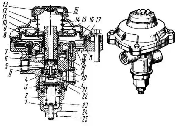
Compressed air from the receiver of the towing vehicle is supplied to terminal “I” and passes through channel A into the cavity above the stepped piston 8.
In the released state, spring 14, acting on plate 15, holds membrane 16 together with pusher 19 in the lower position.
In this case, the outlet valve 20 is closed, and the inlet valve 21 is open and compressed air passes from outlet “I” to outlet “II” and then into the connecting line of the trailer.
When a certain pressure is reached in terminal “II”, set using the adjusting screw 24, the piston 4 overcomes the force of the spring 23 and lowers, as a result of which the inlet valve 21 sits on the seat in the piston 4.
Thus, in the braked position, a certain pressure is automatically maintained in the trailer line, less than the pressure in the pneumatic drive of the tractor.
When the tractor is braking, compressed air is supplied to terminal “IV” and fills the sub-membrane cavity “B”.
Overcoming the force of spring 14, membrane 16 rises up together with pusher 19.
In this case, the inlet valve 21 first closes, and then the outlet valve 20 opens, and the air from the trailer connecting line through terminal “II”, the hollow pusher 19 and terminal “III” in the cover 12 escapes into the atmosphere.
Air leaves port “II” until the pressure in cavity B under the membrane 16 and in the cavity under the stepped piston 8 is balanced by the pressure in the cavity above the stepped piston.
As the pressure at port "II" further decreases, the piston lowers and moves the pusher down, which closes the exhaust valve, as a result of which the release of air from port "II" stops.
In this way, a tracking action is carried out, and the trailer (semi-trailer) is braked with an efficiency proportional to the amount of compressed air pressure supplied to terminal IV.
Further increase in pressure at port "IV" leads to the complete release of compressed air from port "II" and thus to the most effective braking of the trailer.
When the tractor is braked, that is, when the pressure drops at terminal “IV” and in cavity B under the membrane 16, the latter, under the action of the spring 14, returns to its original lower position.
The pusher falls together with the membrane.
This closes the outlet valve and opens the inlet valve 21.
Compressed air from terminal 7 enters terminal "II" and then into the connecting line of the trailer (semi-trailer), as a result of which the trailer (semi-trailer) is released.
Replacing the trailer brake control valve with a single-line drive
The valve must be replaced if the following malfunctions occur:
- - violation of valve tightness. A sign is air leakage through the terminals and where the top cover is attached to the valve body;
- - mechanical damage to the valve body, cover and membrane, interfering with its normal operation
To complete the task you will need keys 17x19 and 22x24
Removing the valve
Turn off the battery switch
Bleeding air from the receivers (Fig. 4) of the parking brake system
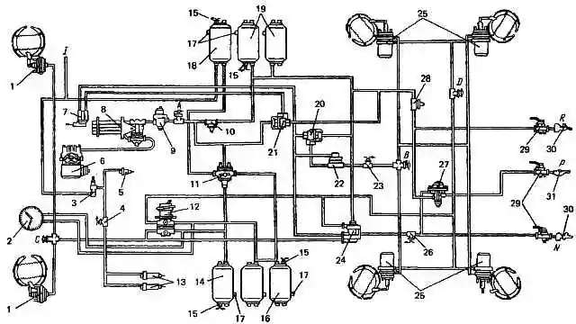
Fig. 4. Diagram of the pneumatic drive of brake systems: 1 - brake chambers type 24; 2 - two-pointer pressure gauge; 3 - valve for controlling the auxiliary brake system; 4 - pneumoelectric switch for the trailer solenoid valve; 5 - pneumatic cylinder for driving the engine stop lever; 6 - compressor; 7 - parking brake system control valve; 5 - water separator; 9 - pressure regulator; 10, 28 - single protective valves; 11 - triple protective valve; 12 - two-section brake valve; 13 - pneumatic cylinders for driving the flaps of the auxiliary brake system mechanism; 14 - receiver of circuit I; 15 - pressure drop warning lamp switches; 16 - receivers of circuit II; 17 - condensate drain taps; 18 - consumer receiver; 19 - receivers of circuit III; 20 - dual-line bypass valve for emergency brake release; 21 - two-line bypass valve; 72 - accelerator valve; 23 - switch for the parking brake system warning lamp; 24 - control valve for trailer brake systems with a two-wire drive; 25 - brake chambers of type 24/24; 26 - brake signal warning lamp switch; 27 - control valve for trailer brake systems with a single-line drive; 29 - disconnect valves; 30 - connecting heads of the “Palm” type; 31 - connecting head type A; A, B, C, D - valves of control terminals; P - to the supply line of the two-wire drive; H - to the connecting line of the single-wire drive; N - to brake (control line of a two-wire drive
Fold back the protective rubber cap and disconnect the ends of the electrical wires from the terminals of switch 26 of the brake signal warning lamp located on the control valve tee
Unscrew the union nuts of the pipelines connected to control valve 27
Unscrew the bolts securing the bracket to the frame and remove the valve
Installing the control valve
Install the bracket onto the valve and secure it with nuts using a 17 mm wrench
Install the control valve assembly with bracket on the rear cross member of the frame and secure it
Connect the pipelines to the terminals of the control valve. Screw and tighten the union nuts
We turn on the car batteries
Start the engine and fill the pneumatic drive of the brake systems with air
Check the tightness of the pipelines and valve. Air leakage is not allowed
")

")
")
")
")
")
")
")