The nozzle is used to spray fuel in accordance with the shape and volume of the combustion chamber
Atomization occurs due to the high speed of flow of fuel under high pressure due to friction when moving through the spray holes and collision with a hot vortex of compressed air
KamAZ engines use closed-type injectors with a locking nozzle needle.
In the intervals between fuel injections, the fuel outlet hole is closed with a needle.
The injector opens only at the moment of injection, when fuel begins to flow to it from the high pressure pump.
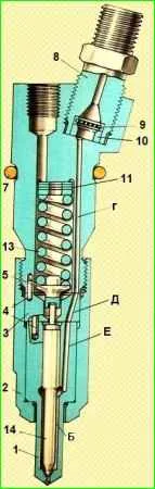
Housing 6 (Fig. 1) of the nozzle is connected to the sprayer with nut 2 through spacer 3.
The multi-jet sprayer consists of a needle 14 and a body 1, in which four sawing holes with a diameter of 0.3 mm (model 33), 0.32 mm (model 271) or 0.33 mm (model 272) are drilled.
These holes are located at different angles to the axis, ensuring uniform distribution of fuel throughout the entire volume of the combustion chamber.
Pair of parts 1 and 14 are precision, the gap between the needle and the sprayer does not exceed 5 microns.
The needle cone rests on the cone of the atomizer body, separating its fuel supply channels and spray holes.
For reliable sealing, the seal cone of the seat in the sprayer is made at an angle of 59 °, and the needle cone is made at an angle of 60 °.
This design of the sealing surfaces of the needle and the sprayer makes it possible to avoid their mutual grinding.
Annular grooves on the nozzle needle guide, trapping leaked fuel and distributing it as a lubricant, improve needle mobility.
The spacer with its pins fixes the nozzle relative to the nozzle body in a strictly defined position, and also limits the stroke of the nozzle needle, which is equal to 0.25 mm.
The locking needle is pressed against the nozzle seat through rod 5 by spring 13.
The upper end of the spring rests against adjusting washers 11, 12.
Fuel is supplied to the injector through fitting 8.
To filter out process contaminants that may enter the fuel line during assembly, a safety filter 9 is installed between the fitting and the injector body.

Having passed the safety filter through the channels: “G” of housing 6, “D” of spacer 3 and “E” of housing 1, the fuel enters the annular chamber under the cone of the needle 14.
Further along the annular gap between the needle and body 1, the fuel flows to the shut-off cone.
When the pressure in chamber “B” acting on the needle cone exceeds the resistance of spring 13, the needle will rise until its end stops against spacer 3, while fuel is injected through the holes of the nozzle body into the combustion chamber of the cylinder.
At the moment the injection pump section stops supplying fuel, the pressure in the annular chamber “B” drops sharply, spring 13 lowers the needle and injection instantly stops.
The pressure at which fuel injection begins is set using adjusting washers 11 and 12.
No more than three shims may be installed.
When the thickness of the pack of adjusting washers increases by 0.05 mm, the injection start pressure increases by 30-50 kPa.
Under the influence of high pressure, a small part of the fuel leaks between the needle and the nozzle body into the cavity of spring 13.
From here, through a channel and a fuel drain drive, it is discharged into the tank.