Synchronizer for fourth and fifth gears of KamAZ vehicle gearbox
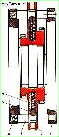
The synchronizer for the fourth and fifth gears (Fig. 1) consists of a synchronizer carriage 2, two friction rings 1 and 4, eight locking pins 3 and eight clamps consisting of springs 6 and clamps 5.
The outer diameter of the synchronizer carriage is processed in the form of a ring, with which it fits into the slots of the gear selector fork legs.
Eight blind radial holes are made around the circumference of the ring, intended for installing springs 6 and clamps 5.
Perpendicular to the blind holes, there are eight holes in the circumference of the ring for installing blocking fingers, and the axes of these holes intersect.
The holes for the locking pins on both sides are chamfered with an angle corresponding to the angle of the chamfers of the locking pins.
The carriage has internal and external gears. The internal rims are designed to move the carriage along the secondary shaft.
In addition, these rings, complete with four rings of the secondary shaft, when engaging fourth or fifth gear, form a “lock” that prevents the transmission from turning off automatically while the car is moving.
The outer rims are made of two diameters.
The ring gear of a smaller diameter is used to connect to the internal gear ring of the input shaft and thereby engage the fifth (direct) gear.
The large diameter ring gear is designed to connect to the ring gear of the fourth gear of the secondary shaft.
Friction rings 1 and 4 have an internal conical surface on which a helical groove is cut to squeeze out lubricant in contact with the cone of the input shaft or gear.
Friction rings are pressed onto the outer ends of the locking fingers until they stop at their ends.
The locking pins 3 also serve as clamps.
In the neutral position, the crackers 5 enter the grooves of the fingers under the action of springs 6.
To move the carriage out of the middle position, force must be applied.
When any gear is engaged, the locking fingers first act as clamps and move the friction rings until they come into contact with the corresponding cone (shaft or gear).
When a friction moment occurs, the carriage rotates relative to the fingers and they begin to act as blockers: the chamfers of the holes rest against the chamfers of the fingers, and the movement of the carriage stops.
After the peripheral speeds have been equalized, the fingers take a neutral position, the carriage, under the action of the gear fork, moves towards the gear being engaged.
The crackers 5 are recessed, compressing the springs 6.
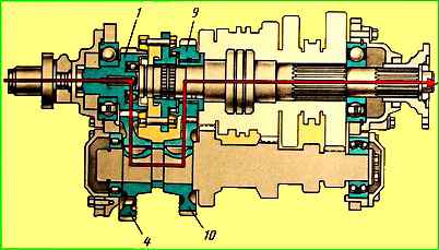
The first gear is engaged by moving the first gear and reverse carriage along the splines of the first gear gear bushing back until it is connected to the ring gear of the first gear gear (Fig. 2).
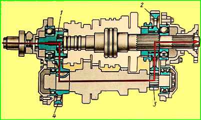
In this case, the torque from the input shaft of the gearbox is transmitted to the intermediate shaft drive gear and then to the first gear gear of the secondary shaft, which is rigidly connected to it through the engaged carriage and bushing.
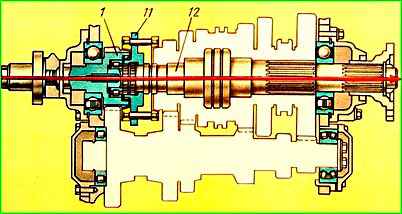
The second gear is engaged by moving the synchronizer carriage of the second and third gears along the splines of the secondary shaft back until it engages with the ring gear of the second gear of the secondary shaft.
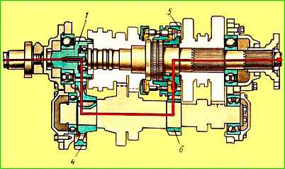
In this case, the second gear The secondary shaft is locked with it through the synchronizer carriage and transmits torque from the second gear of the intermediate shaft.
The third gear is engaged by moving the second and third gear synchronizer carriage forward along the splines of the secondary shaft until it engages with the ring gear of the third gear gear of the secondary shaft.
In this case, the gear is locked with the shaft through the carriage.
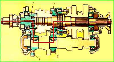
The fourth gear is engaged by moving the fourth and fifth gear synchronizer carriage along the splines of the secondary shaft back until it engages with the ring gear of the fourth gear gear of the secondary shaft.
The fifth gear is engaged by moving the fourth and fifth gear synchronizer carriage forward along the splines of the secondary shaft until it is completely connected to the gear ring of the input shaft.
In this case, the torque from the input shaft is directly transmitted through the synchronizer carriage to the secondary shaft.
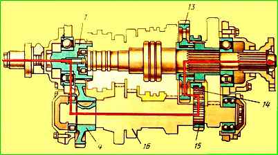
Reverse gear is engaged by moving the first gear carriage and reverse gear along the splines of the first gear bushing forward until it connects with the ring gear of the reverse gear, which is meshed with the reverse gear block.
")

")
")
")
")
")
")
")