KAMAZ vehicles and road trains are equipped with four autonomous braking systems: service, spare, parking and auxiliary
Although these systems have common elements, they operate independently of each other, providing high braking performance in all operating conditions
In what follows we will designate these systems as service, spare, parking and auxiliary brakes.
In addition, KamAZ vehicles are equipped with an emergency brake release drive, which allows the vehicle (road train) to move while automatically braking due to a compressed air leak, an alarm and monitoring devices that allow monitoring the operation of the pneumatic drive.
The service brake is intended for service and emergency braking of the vehicle or stopping it completely.
The service brake drive is pneumatic, dual-circuit, it operates separately the brakes of the front axle and the rear bogie of the vehicle.
The drive is controlled by a foot pedal, mechanically connected to the brake valve.
The actuators of the service brake drive are the brake chambers on the wheels.
The spare brake is intended for service braking or stopping a car and road train; can be used both independently and in case of failure of the service brake.
The parking brake on KamAZ vehicles is made as a single unit with a spare one. To turn it on, the tap handle should be set to the extreme (upper) fixed position.
Thus, on KamAZ vehicles, the brake mechanisms of the rear bogie are common to the service, spare and parking brakes.
The auxiliary brake of a vehicle serves to reduce the load and temperature of the brake mechanisms of the service brake.
The auxiliary brake on KamAZ vehicles is the engine retarder, when activated, the engine inlet pipes are blocked and the fuel supply is turned off.
The emergency brake release system is designed to release spring energy accumulators when they are automatically activated and the vehicle stops due to a compressed air leak in the drive.
The drive of the emergency brake release system is duplicated: in addition to the pneumatic drive, there are mechanical release screws in each of the four spring energy accumulators, which allows them to be turned off mechanically.

The brake mechanism is designed to create artificial resistance to wheel rotation in order to regulate its angular speed or keep it stationary relative to the supporting surface.
All wheels of KamAZ vehicles are equipped with shoe brake mechanisms, characterized by highly stable braking properties.
The shoes are located inside the drums on fixed supports.
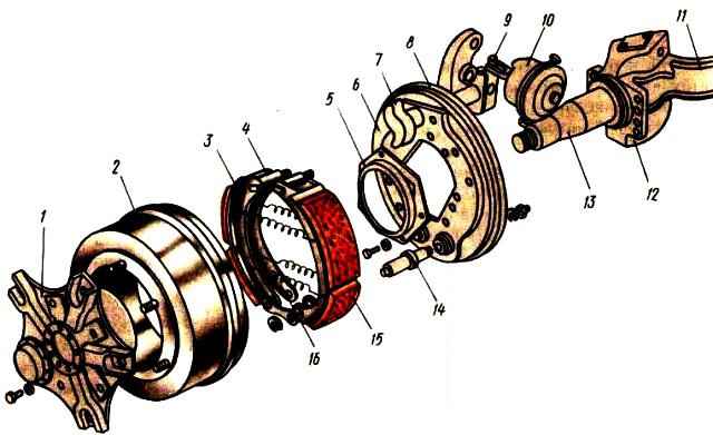
The brake mechanism (Fig. 1) consists of a caliper 6, two pads 3, rollers 4, axles 14, an expansion knuckle 7, a lever 9 with an adjusting mechanism and a drum 2.
The main components of the brake mechanism are mounted on a caliper 6, rigidly connected to the bridge flange 12.
On the eccentric axles 14, fixed to the caliper, two brake pads 3 with friction linings 15 attached to them are freely supported.
The latter are made according to a crescent-shaped profile in accordance with the nature of their wear.
Eccentric axles of the shoes allow the shoes to be correctly aligned with the brake drum when assembling the brake.
When braking, the pads are moved apart by an expanding fist and pressed against the inner surface of the drum, creating resistance to wheel rotation.
To increase braking efficiency and reduce friction, 4 rollers are installed between the expansion fist and the pads.
The pads are returned to their original position by four tension springs 16.
The expansion cam shaft 7 rotates in the bracket on which the brake chamber 10 is installed.
At the end of the expansion cam shaft there is a lever with a worm-type adjusting mechanism connected to the brake chamber rod.
The brake mechanisms of the front wheels differ from the brake mechanisms of the rear wheels in the design of the caliper, the expander body and the expander itself.


